Quick Start Logix5000 Control Systems: Connect POINT I/O Modules over an EtherNet/IP Network Catalog Numbers Logix5000 Controllers, 1734 POINT I/O Modules
Important User Information Solid-state equipment has operational characteristics differing from those of electromechanical equipment. Safety Guidelines for the Application, Installation and Maintenance of Solid State Controls (publication SGI-1.1 available from your local Rockwell Automation sales office or online at http://www.rockwellautomation.com/literature/) describes some important differences between solid-state equipment and hard-wired electromechanical devices.
Table of Contents Preface About This Publication . . . . . . . . . . . . . . . . . . . . . . . . . . . . . . . . . . . . . . . . . . . . 5 Before Using This Publication. . . . . . . . . . . . . . . . . . . . . . . . . . . . . . . . . . . . . . 5 Other Logix5000 Control System Quick Starts . . . . . . . . . . . . . . . . . . . . . . 8 POINT I/O Modules in Device-level Ring or Linear Topology . . . . . . . 8 Before You Begin. . . . . . . . . . . . . . . . . . . . . . . . . . . . . . . . . . . . . . . . . . .
Table of Contents 4 Rockwell Automation Publication IASIMP-QS027A-EN-P - February 2012
Preface About This Publication This quick start provides examples and procedures for including POINT I/O modules in a Logix5000 control system over an EtherNet/IP network. The programming examples are not complex, and offer easy solutions to verify that devices are functioning and communicating properly. IMPORTANT This publication describes example tasks you complete when using POINT I/O modules on an EtherNet/IP network.
Preface For more information on how to complete the prerequisite tasks with specific Logix5000 controllers, see the Integrated Architecture : Logix5000 Control Systems Quick Starts Quick Reference, publication IASIMP-QR024. Table 1 - Required Tasks To Complete Before Using this Quick Start Task Description Prepare the Logix5000 Assembling the control system and connecting to necessary communication networks.
Preface Table 1 - Required Tasks To Complete Before Using this Quick Start Task Description Configure the networks Complete required tasks associated with the networks used in your application, such as assigning an IP address to the controller or a communication module in your Logix5000 control system.
Preface Other Logix5000 Control System Quick Starts This quick start describes how to add one device on one network in a Logix5000 control system. Typically, though, a Logix5000 control system includes more than one device on one network. For example, if a Logix5000 control system operates on an EtherNet/IP network, in addition to a controller, power supply, and communication modules, the system might use remote I/O modules, drives, or HMI terminals.
Preface Where to Start Prerequisite Tasks Described in Before Using This Publication on page 5. 1. Prepare the Logix5000 control system hardware. 2. Prepare the computer. 3. Configure the networks. 4. Create an RSLogix 5000 project.
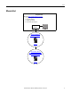
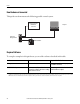
Preface How Hardware is Connected This quick start demonstrates the following possible control system.
Preface Parts List To complete the tasks described in this publication, you need the parts listed in this table. Quantity Cat. No.
Preface Table 2 - Additional Resources Resource Description FLEX I/O DC Power Supply Installation Instructions, publication 1794-IN069 Describes how to install the 1794-PS and 1794-PS13 power supplies. Logix5000 Controllers Common Procedures Programming Manual, publication 1756-PM001 Provides details about adding and configuring modules, establishing communication, and writing ladder logic.
Chapter 1 Prepare the Distributed POINT I/O Module Hardware In this chapter, you learn how to complete the following tasks: • Install the 1734-AENT Ethernet adapter • Install the 1734-OB4E digital output module • Install a 1794-PS3 FLEX I/O power supply • Connect power to the 1734-AENT Ethernet adapter Before You Begin You must complete these tasks before using this chapter: • The tasks described in Before Using This Publication on page 5, including: – Prepare the Logix5000 control system hardware – Pre
Chapter 1 Prepare the Distributed POINT I/O Module Hardware What You Need The following table lists the products that you need to complete the tasks described in this chapter. Quantity Cat. No.
Prepare the Distributed POINT I/O Module Hardware Chapter 1 Follow These Steps Mount and Connect the 1734-AENT Ethernet Adapter page 16 8 7 6 5 4 3 2 1 Mount the 1734-OB4E Digital Output Module page 17 Mount and Wire the 1794-PS3 Power Supply page 18 Module Status 00 2 Network Activity Status Network Status PointBus Status 24VDC Source Output 1734-AENT Wire the 1734-AENT Ethernet Adapter to the Power Supply System Power page 19 Rockwell Automation Publication IASIMP-QS027A-EN-P - February
Chapter 1 Prepare the Distributed POINT I/O Module Hardware Mount and Connect the 1734-AENT Ethernet Adapter 1. Position the adapter vertically in front of the DIN rail and press firmly onto the DIN rail until the adapter locks into place. 2. To set the module’s IP address to a valid number, set the module’s thumbwheel switches to a number between 001 and 254.
Prepare the Distributed POINT I/O Module Hardware Chapter 1 Mount the 1734-OB4E Digital Output Module 1. Install the removable terminal base (RTB) on the mounting base. Make sure the handle is in the down position. 2. Using a small screwdriver, rotate the keyswitch on the mounting base to match the position on the keyswitch on the I/O module. Handle This example shows the keyswitch in position 1. Mounting Base Removable Terminal Block 3. Press the 1734-OB4E module into the wiring base. Module 4.
Chapter 1 Prepare the Distributed POINT I/O Module Hardware Mount and Wire the 1794-PS3 Power Supply Use a 1794 FLEX I/O power supply to power the distributed POINT I/O modules. This publication uses the 1794-PS3 power supply. 1794-PS3 Power Supply WARNING: Verify that all incoming power is turned off before wiring power. 1. Hook the upper-lip of the DIN rail latch onto the DIN rail. 2. Press the module onto the DIN rail next to the POINT I/O Ethernet adapter. 3.
Prepare the Distributed POINT I/O Module Hardware Chapter 1 Wire the 1734-AENT Ethernet Adapter to the Power Supply 1. Connect the 12/24V DC common and 12/24V DC power wires from the power supply to the adapter. Module Status 00 2 Network Activity Status Network Status PointBus Status 24VDC Source Output 1734-AENT 2. Turn on incoming power.
Chapter 1 Prepare the Distributed POINT I/O Module Hardware Notes: 20 Rockwell Automation Publication IASIMP-QS027A-EN-P - February 2012
Chapter 2 Add the POINT I/O Ethernet Adapter and Digital Output Module to an RSLogix 5000 Project In this chapter, you complete the following tasks: • Add the 1734-AENT Ethernet adapter to the RSLogix 5000 project • Add the 1734-OB4E digital output module to the RSLogix 5000 project • Use ladder logic to test the 1734-OB4E digital output module’s lights Before You Begin You must complete these tasks before using this chapter: • The tasks described in Before Using This Publication on page 5, including: –
Chapter 2 Add the POINT I/O Ethernet Adapter and Digital Output Module to an RSLogix 5000 Project What You Need You need RSLogix 5000 software to complete the tasks in this chapter.
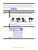
Add the POINT I/O Ethernet Adapter and Digital Output Module to an RSLogix 5000 Project Chapter 2 Configure the POINT I/O Adapter and Output Module 1. Open your RSLogix 5000 project and verify that it is Offline with the controller. 2. Right-click Ethernet in the I/O Configuration folder and choose New Module. 3. Select the 1734-AENT Ethernet adapter and click Create. 4. Type the name for the adapter. 5. Type the adapter’s IP address. 6. Click Change.
Chapter 2 Add the POINT I/O Ethernet Adapter and Digital Output Module to an RSLogix 5000 Project 7. Make these changes on the Module Definition dialog box. a. Select the Series. b. Select the Revision. c. Select the Chassis Size. Chassis size equals the number of POINT I/O modules + 1 for the adapter. In this example, the Chassis Size is 2 to account for the 1734-AENT Ethernet adapter and the 1734-OB4E digital output module. d. Select Disable Keying. e. Click OK.
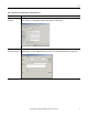
Add the POINT I/O Ethernet Adapter and Digital Output Module to an RSLogix 5000 Project Chapter 2 9. Right-click the 1734-AENT Ethernet adapter and choose New Module. 10. Select the 1734-OB4E digital output module and click Create. 11. Configure the following parameters: • • • Name Slot (Slot number is the position of the module to the right of the adapter.) Electronic Keying 12. Click OK. The 1734-OB4E digital output module is added to the I/O configuration. 13. Save the project.
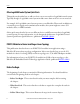
Chapter 2 Add the POINT I/O Ethernet Adapter and Digital Output Module to an RSLogix 5000 Project Add Ladder Logic to Test the 1734-OB4E Module’s Lights 1. In RSLogix 5000 software’s controller organizer, expand Tasks >MainTask>MainProgram. 2. Double-click MainRoutine. A blank routine opens. 3. Add a new rung to the routine. 4. From the Element Toolbar, drag and drop an Examine On element and an Output Energize element onto the rung. 5. Double-click the ? in the Examine On element. 6.
Add the POINT I/O Ethernet Adapter and Digital Output Module to an RSLogix 5000 Project Chapter 2 8. Right-click PB and choose New “PB”. 9. When the New Tag dialog box appears, click Create and Close to use the default values. 10. Double-click the ? in the Output Energize element. 11. Name the Output Energize element OB4E_Light. IMPORTANT Do not use spaces in the tag name. Use underscores (__) instead.
Chapter 2 Add the POINT I/O Ethernet Adapter and Digital Output Module to an RSLogix 5000 Project 12. Right-click the OB4E_Light tag and choose New “OB4E_Light”. OB4E_Light is an alias tag for the I/O point tag name. With an alias tag, you can assign a simple name to a physical I/O point address. 13. From the Type pull-down menu, choose Alias. 14. From the Alias For pull-down menu, browse to the 1734-OB4E digital output module and choose any bit. This example uses my_aent:1:O.Data[0]. 15.
Add the POINT I/O Ethernet Adapter and Digital Output Module to an RSLogix 5000 Project Chapter 2 Download the Project to Your Logix5000 Controller 1. Save your changes. 2. Move the controller’s switch to Program. RUN REM PROG 3. Click the Controller Status icon and choose Download. 4. Click Download.
Chapter 2 Add the POINT I/O Ethernet Adapter and Digital Output Module to an RSLogix 5000 Project Test the 1734-OB4E Output Module’s Light 1. Move the controller’s mode switch to the RUN position. 2. If not open, open the project’s Main Routine to find the ladder logic written earlier in this chapter. 3. Select the PB and press Ctrl+T. This toggles the state from 0 to 1 (off to on). 4. Verify that the light on the distributed digital output module turns on. 5.
Index B BOOTP/DHCP utility 10 C connections hardware 10 conventions 11 D DLR topology 8 N network topologies DLR 8 linear 8 P parts required to complete tasks 11 power supply connect 18 prerequisite tasks 5-7 Q E Ethernet adapter assign IP address 16, 23 connect 16 quick starts for devices in Logix5000 control systems 8 R H hardware connect Ethernet adapter 16 connect I/O modules 17 connect power supply 18 install removable terminal base 17 preparation 13-19 removable terminal base keyswitch 17 I I
Index Notes: 32 Rockwell Automation Publication IASIMP-QS027A-EN-P - February 2012
Rockwell Automation Support Rockwell Automation provides technical information on the Web to assist you in using its products. At http://www.rockwellautomation.com/support/, you can find technical manuals, a knowledge base of FAQs, technical and application notes, sample code and links to software service packs, and a MySupport feature that you can customize to make the best use of these tools.