Quick Start Logix5000 Control Systems: Connect a PanelView Plus Terminal over an EtherNet/IP Network Catalog Numbers Logix5000 Controllers, 2711P PanelView Plus Terminals
Important User Information Solid-state equipment has operational characteristics differing from those of electromechanical equipment. Safety Guidelines for the Application, Installation and Maintenance of Solid State Controls (publication SGI-1.1 available from your local Rockwell Automation sales office or online at http://www.rockwellautomation.com/literature/) describes some important differences between solid-state equipment and hard-wired electromechanical devices.
Table of Contents Preface Before Using This Publication . . . . . . . . . . . . . . . . . . . . . . . . . . . . . . . . . . . . . . 5 Other Logix5000 Control System Quick Starts . . . . . . . . . . . . . . . . . . . . . . . 8 Use Each Chapter . . . . . . . . . . . . . . . . . . . . . . . . . . . . . . . . . . . . . . . . . . . . . . . . . . 8 Where to Start . . . . . . . . . . . . . . . . . . . . . . . . . . . . . . . . . . . . . . . . . . . . . . . . . . . . . 9 How Hardware Is Connected . . . . . . . . .
Table of Contents Notes: 4 Rockwell Automation Publication IASIMP-QS033A-EN-P - March 2012
Preface This quick start provides examples and procedures for including a PanelView Plus terminal in a Logix5000 control system over an EtherNet/IP network. The programming examples are not complex, and offer easy solutions to verify that devices are functioning and communicating properly. IMPORTANT This publication describes basic example tasks you can complete when using a PanelView Plus terminal on an EtherNet/IP network.
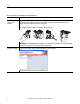
Preface Table 1 - Required Tasks To Complete Before Using This Quick Start Task Description Prepare the Logix5000 Assemble the control system and connect to necessary communication networks. Some components, for control system example, the desired Logix5000 controller and system power supply, are required. Other components, for hardware example, a network communication module, are optional. These graphics show the assembly of an example Logix5000 controller.
Preface Table 1 - Required Tasks To Complete Before Using This Quick Start Task Description Configure the networks Complete required tasks associated with the networks used in your application. For instance, as assign an IP address to the controller or to a communication module in your Logix5000 control system. Create an RSLogix 5000 project Create a project to be used with your Logix5000 controller. A project includes all desired control system components and necessary programming.
Preface Other Logix5000 Control System Quick Starts This quick start describes how to use one device on one network in a Logix5000 control system. Typically, though, a Logix5000 control system includes more than the controller and one device on one network. For example, if a Logix5000 control system operates on an EtherNet/IP network, in addition to a controller, power supply, and communication modules, the system might use remote I/O modules, drives and HMI terminals.
Preface Where to Start Prerequisite Tasks Described in Before Using This Publication on page 5. 1. Prepare the Logix5000 control system hardware. 2. Prepare the computer. 3. Configure the networks. 4. Create an RSLogix 5000 project.
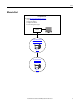
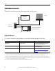
Preface How Hardware Is Connected This quick start demonstrates the following possible control system. Computer Logix5000 Controller with Ethernet Connection Stratix 6000 Managed Switch 8 7 6 5 4 3 2 1 PanelView Plus Terminal with Built-in EtherNet/IP Port Required Software To complete examples in this quick start, you need the software described in this table. Software Version Required for This Task RSLogix 5000 20.00.
Preface Parts List You need these parts to use this publication. Quantity Cat. No. Description 1 2711P-K10C4D1 PanelView Plus 1000 with built-in EtherNet/IP network port 1 2711P-RSACDIN DC power supply for PanelView Plus terminals 1 Panel for mounting the terminal, if desired - To complete the tasks described in this quick start, you can prop the PanelView Plus terminal on a desktop.
Preface Notes: 12 Rockwell Automation Publication IASIMP-QS033A-EN-P - March 2012
Chapter 1 Prepare the PanelView Plus Terminal Hardware In this chapter, you learn how to complete the following tasks: • Mount and wire power to a 2711P-K10C4D1 terminal. • Configure EtherNet/IP communication for the terminal.
Chapter 1 Prepare the PanelView Plus Terminal Hardware Follow These Steps Mount the PanelView Plus Terminal page 14 – Connect the Power Supply page 15 + GND GND Connect the PanelView Plus Terminal to the EtherNet/IP Network 8 7 6 5 4 3 2 1 page 16 Assign an IP Address to the PanelView Plus Terminal page 16 Mount the PanelView Plus Terminal In normal applications, you mount a PanelView Plus terminal to a panel.
Prepare the PanelView Plus Terminal Hardware Chapter 1 Connect the Power Supply WARNING: Verify that all incoming power is turned off before wiring power. This quick start uses a PanelView Plus 1000 terminal with built-in Ethernet port and a PanelView Plus Logic module, catalog number 2711P-RP1, Series G. The 2711P-RP1 Logic module uses a 2-position terminal block for power connections.
Chapter 1 Prepare the PanelView Plus Terminal Hardware 2. Gently pull the terminal block off of the PanelView Plus terminal. 3. Connect the 12/24V DC common and 12/24V DC power wires from the power supply to the terminal block, - (common) and + (power). PanelView Plus + 24V DC POWER SUPPLY 2711P-RSACDIN POWER 4. Connect the terminal block to the PanelView Plus terminal.
Prepare the PanelView Plus Terminal Hardware Chapter 1 Assign an IP Address to the PanelView Plus Terminal This graphic shows a 2711P-RP1, Series G terminal. You use the keypad buttons to make choices from the options on the terminal screen. • If the options on the screen are lines of text, press the direction arrows, that is, up/down and left/right arrows, on the keypad to highlight the option you need and press the enter button.
Chapter 1 Prepare the PanelView Plus Terminal Hardware Complete the following steps to assign an IP address to the PanelView Plus terminal. 1. Apply power to the PanelView Plus terminal. 2. When the initial PanelView Plus terminal configuration screen appears on the terminal, press [F4] on the keypad to access the terminal settings. 3.
Prepare the PanelView Plus Terminal Hardware Chapter 1 10. Press OK [F7] to save settings, as shown, and press OK [F7] to acknowledge the reset message. 11. Press [F8] four times until you return to the initial configuration screen. 12. Press [F7] to reset the terminal. 13. Press [F7] to confirm. Additional Resources For a list of additional resources that might assist you when preparing the PanelView Plus terminal hardware, see page 11.
Chapter 1 Prepare the PanelView Plus Terminal Hardware Notes: 20 Rockwell Automation Publication IASIMP-QS033A-EN-P - March 2012
Chapter 2 Create a PanelView Plus Application In this chapter, you learn how to complete the following tasks: • Create a push button and a multi-state indicator in FactoryTalk View Studio software. • Transfer the application to the 2711P-K10C4D1 drive so you can test communication with the controller.
Chapter 2 • Create a PanelView Plus Application Install an I/O module with the following conditions: – Accessible to the PanelView Plus terminal over the EtherNet/IP network – Included in the RSLogix 5000 project used with this quick start. This publication uses a 1769-OB16 digital output module.
Create a PanelView Plus Application Chapter 2 Follow These Steps Install FactoryTalk View Studio Test the Indicator and Push Button page 24 Install RSLinx Enterprise Software page 40 Add a Goto Configuration Mode Button page 28 Create a New Application page 43 Assign Function Keys page 45 page 30 Create an RSLinx Enterprise Configuration in FactoryTalk View Machine Edition Assign an Initial Screen page 31 Create a Device Shortcut to the Controller page 46 Transfer to PanelView Plus Terminal pa
Chapter 2 Create a PanelView Plus Application Install FactoryTalk View Studio Software IMPORTANT The tasks described in this quick start use a 1769-L36ERM controller. That controller requires that you use FactoryTalk View Studio software, version 6.00.00. Therefore, this chapter describes how to use FactoryTalk View Studio software, version 6.00.00. You can use FactoryTalk View Studio software, version 5.01.00 or earlier (known as FactoryTalk View Studio software) with some Logix5000 controllers.
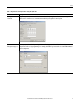
Create a PanelView Plus Application Chapter 2 3. Click Install FactoryTalk View Site Edition. 4. Click Install FactoryTalk View Site Edition. All Rockwell Automation software products should be shutdown, as described in step 1. If they are not, the software alerts you to this requirement. 5. Click Yes. 6. Click Next.
Chapter 2 Create a PanelView Plus Application 7. Read the end-user license agreement. 8. Check I accept the terms in the license agreement and click Next. 9. Enter your user name, organization, and software serial number and click Next. 10. Select Complete and click Next.
Create a PanelView Plus Application Chapter 2 11. Select the Destination Drive and click Next. We recommend you use the default Destination Drive setting. 12. Click Install. 13. When the InstallShield Wizard Completed dialog box appears, click Finish. You have the option to Install FactoryTalk Activation Server.
Chapter 2 Create a PanelView Plus Application Install RSLinx Enterprise Software IMPORTANT Your computer must have RSLinx Enterprise software to use FactoryTalk View Studio software. Immediately following the end of installing FactoryTalk View Studio software, the installation process for RSLinx Enterprise software begins automatically. Throughout the installation, click Next to use default RSLinx Enterprise software installation settings, except when indicated in the following steps.
Create a PanelView Plus Application Chapter 2 4. Enter your user name, organization, and software serial number and click Next. 5. Choose the software setup type and click Next. We recommend you use Standard Feature Set Installation, as shown. 6. Click Install.
Chapter 2 Create a PanelView Plus Application 7. When the InstallShield Wizard Completed dialog box appears, click Finish. You must restart the computer to complete the installation process. 8. Restart your computer. Create a New Application 1. Launch FactoryTalk View Studio software. 2. On the Application Type Selection dialog box, select Machine Edition and click Continue.
Create a PanelView Plus Application Chapter 2 3. Select the New tab. 4. Name the application (do not use spaces) and click Create. Create an RSLinx Enterprise Configuration in FactoryTalk View Machine Edition 1. In the FactoryTalk View organizer, expand RSLinx Enterprise and double-click Communication Setup. 2. Click Finish. RSLinx Enterprise software opens.
Chapter 2 Create a PanelView Plus Application The Design (Local) tab defines the path from the computer to the controller. The Runtime (Target) tab defines the path from the PanelView Plus terminal to the controller. Local Computer Target Logix5000 Controller The computer needs to communicate with the controller when you are in Test Run mode. This path is defined on the Local tab.
Create a PanelView Plus Application Chapter 2 Create a Device Shortcut to the Controller 1. Expand the EtherNet/IP tree, select your controller and click Add. 2. Type a shortcut name; do not use spaces. 3. Verify that the controller you selected in step 1 is still selected. 4. Click Apply. 5. Click Copy from Design to Runtime. 6. Click OK.
Chapter 2 Create a PanelView Plus Application Create the OB16_Light Indicator 1. Verify that you have created an RSLogix 5000 project that includes an output module and a ladder logic rung with Examine On and Output Energize elements similar to the one shown. This example, the alias tag named OB16_Light is an alias for point Local:1:O:Data.0. You might choose to use a different point on the module. If so, verify that the alias tag is set to the correct module point. 2.
Create a PanelView Plus Application Chapter 2 6. Click and drag to create the indicator. 7. Right-click and choose Properties. 8. On the General tab, select 2 for the Number of states. 9. On the States tab, verify that State0 is selected. 10. In the Caption, type Light is OFF.
Chapter 2 Create a PanelView Plus Application 11. Select State1. 12. In the Caption, type Light is ON. 13. Change the Back Color to yellow. 14. Change the Caption Color to black. 15. On the Connections tab, click ... under Tag. The Tag Browser dialog box appears. 16. Right-click your project and select Refresh All Folders.
Create a PanelView Plus Application Chapter 2 17. Expand the controller shortcut and select the Online folder. The tags created in your RSLogix 5000 project, as described on page 21, appear to the right. IMPORTANT If the tags in your RSLogix 5000 project do not appear, verify that they were created at the controller scope and not the Main Program scope in RSLogix 5000 software. 18. Select the OB16_Light tag. 19. Click OK. The Indicator tag is populated. 20. Click OK.
Chapter 2 Create a PanelView Plus Application Create a Push Button 1. From the Objects menu, select Push Button Maintained. 2. Click and drag to create the push button beneath the indicator. 3. Right-click the push button you just created and select Properties. 4. On the States tab, verify that State0 is selected. 5. In the Caption, type Push to turn light ON.
Create a PanelView Plus Application Chapter 2 6. Select State1. 7. In the Caption, type Push to turn light OFF. 8. On the Connections tab, click ... under Tag in the Value row. The Tag Browser dialog box appears. 9. Expand the controller shortcut and select the Online folder. The tags created in your RSLogix 5000 project, as described on page 21, appear to the right. 10. Select the PB tag. 11. Click OK.
Chapter 2 Create a PanelView Plus Application The Indicator tag is populated. 12. Click OK. 13. From the File menu, choose Save. 14. When prompted for a display title, type PanelView_Plus_project. Test the Indicator and Push Button 1. Verify that the mode switch on your controller is moved to Run. 2. Right-click an unused area of the display and select Display Settings. 3. Change the Maximum Tag Update Rate to 0.05. 4. Click OK.
Create a PanelView Plus Application Chapter 2 A message appears warning you that the Update Rate changes take effect only after the display is reopened. 5. Click OK. 6. Save the display and close it. 7. Double-click the display name, PanelView_Plus_project in this case, to reopen the display. 8. Click the Play button.
Chapter 2 Create a PanelView Plus Application 9. Click the push button to toggle the state and turn the light on and off. 10. Click the Stop button.
Create a PanelView Plus Application Chapter 2 Add a Goto Configuration Mode Button 1. From the Objects menu, choose Advanced Goto Configure Mode. 2. Click and drag to create the Goto button next to the push button. 3. Right-click the push button and select Properties.
Chapter 2 Create a PanelView Plus Application 4. On the Label tab, enter Goto Config for the caption. 5. Click OK. The Goto Config button appears.
Create a PanelView Plus Application Chapter 2 Assign Function Keys If your PanelView Plus does not have a touch screen, you must assign functions keys to the display buttons. This publication uses a PanelView Plus 1000, catalog number 2711P-K10C4D1. That terminal does not have a touch screen. To assign function keys, complete these steps. 1. Right-click the push button and select Key Assignments. 2. Under Select an object, verify that MaintainedPushButton is selected. 3.
Chapter 2 Create a PanelView Plus Application 4. Under Select an object, select GotoConfigureMode. 5. Select a different function key and click Apply. This example uses F3. 6. Click OK. 7. Access the button properties to add the function key names to them, including both states of the indicator. 8. Save your changes. Assign an Initial Screen 1. Under System folder, double-click Startup.
Create a PanelView Plus Application Chapter 2 2. Check Initial graphic and select PanelView_Plus_project, or the initial display name if different, from the pull-down menu. 3. Click OK. 4. Save your changes. Transfer to PanelView Plus Terminal 1. From the Application menu, choose Create Runtime Application. 2. In Save as type, select the Runtime version that matches your PanelView Plus firmware.
Chapter 2 Create a PanelView Plus Application 4. From the Tools menu, choose Transfer Utility. 5. Click the ... button. 6. Select the .mer file you just created and click Open. 7. Verify the following: • • • Run application when download completes is checked Replace communications is checked Your PanelView Plus is selected for the destination terminal 8. Click Download. The download process may take a few minutes.
Create a PanelView Plus Application Chapter 2 9. When the Transfer Utility dialog box appears, click OK. 10. Exit the Transfer Utility. Test the Application on the PanelView Plus Terminal 1. On the PanelView Plus terminal, press Load Application [F1]. 2. Select your .mer file and press Load [F2]. 3. Press Yes [F7]. 4. After the application loads, press Run Application [F2].
Chapter 2 Create a PanelView Plus Application 5. Press the push button and verify that the indicator turns on and that the light on the Compact digital output module turns on. 6. Press the push button again and verify that the indicator and light turn off. Additional Resources For a list of additional resources that might assist you when creating a PanelView Plus application, see page 11.
Index C connections hardware 10, 15-16 E P parts PanelView Plus terminal 11 required to complete tasks 11 power connect to terminal 15-16 Ethernet adapter assign IP address 17-19 connect terminal to network 16 F FactoryTalk View Machine Edition requirements 10 FactoryTalk View Studio software install 24-27 H hardware connect Ethernet adapter 16 example control system 10 mount terminal 14 preparation 13-16 required parts 11 wire power 15-16 I IP address assign to Ethernet adapter 17-19 L Q quick star
Index Notes: 52 Rockwell Automation Publication IASIMP-QS033A-EN-P - March 2012
Rockwell Automation Support Rockwell Automation provides technical information on the Web to assist you in using its products. At http://www.rockwellautomation.com/support/, you can find technical manuals, a knowledge base of FAQs, technical and application notes, sample code and links to software service packs, and a MySupport feature that you can customize to make the best use of these tools.