Quick Start Logix5000 Control Systems: Connect Kinetix 5500 Drives over an EtherNet/IP Network Catalog Numbers Logix5000 Controllers, Kinetix 5500 Drives
Important User Information Solid-state equipment has operational characteristics differing from those of electromechanical equipment. Safety Guidelines for the Application, Installation and Maintenance of Solid State Controls (publication SGI-1.1 available from your local Rockwell Automation sales office or online at http://www.rockwellautomation.com/literature/) describes some important differences between solid-state equipment and hard-wired electromechanical devices.
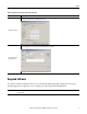
Table of Contents Preface About This Publication . . . . . . . . . . . . . . . . . . . . . . . . . . . . . . . . . . . . . . . . . . . . Before Using This Publication. . . . . . . . . . . . . . . . . . . . . . . . . . . . . . . . . . . . . . Required Software. . . . . . . . . . . . . . . . . . . . . . . . . . . . . . . . . . . . . . . . . . . . . . . . . How Hardware is Connected . . . . . . . . . . . . . . . . . . . . . . . . . . . . . . . . . . . . . . Where to Start . . . . . . . . . . . . . . . . . . .
Table of Contents Notes: 4 Rockwell Automation Publication IASIMP-QS035A-EN-P - December 2012
Preface About This Publication This quick start provides examples and procedures for integrating a Kinetix® 5500 drive into any Logix5000™ control system over an EtherNet/IP network. The programming examples are not complex and offer easy solutions to verify that devices are functioning and communicating properly. IMPORTANT This publication describes example procedures you can complete when using a Kinetix 5500 drive over an EtherNet/IP network.
Preface Before Using This Publication Before using this quick start, you need to install and configure the Logix5000 controller, install the Studio 5000 Logix Designer application, configure the controller network, and create a project file for your application. IMPORTANT The example graphics shown are for CompactLogix™ 5370 L3 controllers. Depending on the Logix5000 controller you are using, the specific steps to complete the tasks described in the table may be different.
Preface Tasks to Complete before Using This Quick Start (continued) Task Description Configure the controller network used in your application. This involves assigning an IP address to the controller’s communication port or communication module used in your Logix5000 control system. Configure the networks Create a project to be used with your Logix5000 controller. A project includes all desired control system components and necessary programming.
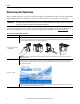
Preface How Hardware Is Connected This example control system uses a Kinetix 5500 standalone drive.
Preface Where to Start Prerequiste Tasks Described in Before Using This Publication 00:00:BC:2E:69:F6 1 (Front) 2 (Rear) page 6 Logix5000 Controller Logix Designer Application Chapter 1 Prepare the Kinetix 5500 Drive Hardware page 11 Chapter 2 Add a Kinetix 5500 Drive to a Logix Designer Application page 31 Additional Resources Resource Description Kinetix 5500 Servo Drives User Manual, publication 2198-UM001 Describes how to install, wire, configure, operate, and troubleshoot your Kinetix 5500 dr
Preface Notes: 10 Rockwell Automation Publication IASIMP-QS035A-EN-P - December 2012
Chapter 1 Prepare the Kinetix 5500 Drive Hardware In this chapter, you mount the Kinetix 5500 servo drive to your panel, make input power, motor, Ethernet, and other connections at the drive, and configure the servo drive IP address for communication over the EtherNet/IP network. Before You Begin Complete the prerequisite tasks related to the Logix5000 controller and Logix Designer application described in the Preface.
Chapter 1 Prepare the Kinetix 5500 Drive Hardware Follow These Steps Prepare the Panel page 13 Apply the Single Motor Cable Shield Clamp Mount the Kinetix 5500 Drive page 26 page 14 Connect the Kinetix 5500 Drive to the EtherNet/IP Network Ground the Kinetix 5500 Drive page 28 page 17 Assign an IP Address to the Kinetix 5500 Drive L3 ove Rem DC For Only Bus Wire Drive Connectors L2 page 29 L1 page 18 12 Rockwell Automation Publication IASIMP-QS035A-EN-P - December 2012 PRECHARGE 192.168.1.
Prepare the Kinetix 5500 Drive Hardware Chapter 1 Prepare the Panel Mount your 2198-Hxxx-ERS servo drive on a paint-free grounded panel along with your Logix5000 controller. For more information on installing a panel for use with a Kinetix 5500 servo drive, refer to the Kinetix 5500 Servo Drives User Manual, publication 2198-UM001.
Chapter 1 Prepare the Kinetix 5500 Drive Hardware Mount the Kinetix 5500 Drive 1. Verify that you have met the minimum clearance requirements required for mounting your 2198-Hxxx-ERS servo drive. • Additional clearance is required for cables and wires or the shared-bus connection system connected to the top of the drive. • Additional clearance is required if other devices are installed above and/or below the drive and have clearance requirements of their own.
Prepare the Kinetix 5500 Drive Hardware Chapter 1 Dimensions - Kinetix 5500 Servo Drives Dimensions are in mm (in.) E B 2198-H003-ERS servo drive is shown. 3.0 (0.12) C A D Kinetix 5500 Drive Cat. No. 2198-H003-ERS 2198-H008-ERS A mm (in.) B mm (in.) 50 (1.97) 170 (6.69) 55 (2.16) 225 (8.86) 85.2 (3.35) 250 (9.84) 2198-H015-ERS 2198-H025-ERS C mm (in.) D mm (in.) E mm (in.) 215 (8.46) 200 (7.87) 226 (8.90) 265 (10.
Chapter 1 Prepare the Kinetix 5500 Drive Hardware 2. Drill the hole pattern for your frame 1, frame 2, or frame 3 standalone drive. Frame 1 Standalone Drive 4.51 (0.2) 8x ØM4 (#8-32) 272.0 (10.7) 243.84 (9.6) 193.68 (7.6) Frame 3 Standalone Drive Frame 2 Standalone Drive 34.00 (1.3) 5.00 (0.2) 0 0 0 Dimensions are in mm (in.) 0 0 0 52.50 (2.1) These hole patterns are only for standalone drive installations.
Prepare the Kinetix 5500 Drive Hardware Chapter 1 Ground the Kinetix 5500 Drive 1. Ground Kinetix 5500 drives to a bonded cabinet ground bus with a braided ground strap or 4.0 mm2 (12 AWG) copper wire. Kinetix 5500 Servo Drive (standalone) Multiple standalone drives using zero-stack feature. Item Description 1 Ground screw (green) 2.0 N•m (17.
Chapter 1 Prepare the Kinetix 5500 Drive Hardware Wire Drive Connectors Kinetix 5500 servo drives are capable of 200V-class (single/three-phase) and 400V-class (three-phase) operation. This wiring diagram is for 200/400V-class, three-phase operation. For additional interconnect wiring diagrams, refer to the Kinetix 5500 Servo Drives User Manual, publication 2198-UM001.
Prepare the Kinetix 5500 Drive Hardware Chapter 1 Wiring Guidelines Follow these steps when wiring the connectors for your Kinetix 5500 drive. 1. Prepare the wires for attachment to each connector plug by removing insulation equal to the recommended strip length. IMPORTANT When removing insulation from wires and tightening screws to secure the wires, refer to the tables provided for strip lengths and torque values. Use caution not to nick, cut, or otherwise damage strands as you remove the insulation.
Chapter 1 Prepare the Kinetix 5500 Drive Hardware Wire the Input Power Connector The input power (IPD) connector requires 195…528V AC (single-phase or three-phase) for mains input power. ATTENTION: Make sure the input power connections are correct when wiring the IPD connector plug and that the plug is fully engaged in the drive connector. Incorrect wiring/polarity or loose wiring can cause explosion or damage to equipment.
Prepare the Kinetix 5500 Drive Hardware Chapter 1 Disable the Safe Torque-off Feature The safe torque-off circuit is designed to safely turn off all of the output-power transistors. Each Kinetix 5500 drive ships with two 5-pin wiring plugs for wiring to safety devices. If your application, for example, the one used in this quick start, does not include safety devices, you must disable the safe torque-off feature. The safe torque-off (STO) connector uses spring tension to secure the wire.
Chapter 1 Prepare the Kinetix 5500 Drive Hardware Wire the Digital Inputs Connector The digital inputs (IOD) connector uses spring tension to hold wires in place. Kinetix 5500 Servo Drive (front view) IN1 COM IN2 SHLD 1 Digital Inputs (IOD) Connector Plug Digital Inputs (IOD) Connector Specifications Drive Cat. No. DC Pin Signal Recommended Wire Size mm2 (AWG) Strip Length mm (in.) Torque Value N•m (lb•in) 2198-Hxxxx-ERS IOD-1 IOD-2 IOD-3 IOD-4 IN1 (1) COM IN2 SHLD 1.5…0.2 (16…24) 10.0 (0.
Prepare the Kinetix 5500 Drive Hardware Chapter 1 Motor Power Connections Kinetix 5500 Servo Drive (front view) U V Motor Power (MP) Connector Plug W Motor Cable Shield Clamp ATTENTION: Make sure the motor power connections are correct when wiring the MP connector plug and that the plug is fully engaged in the module connector. Incorrect wiring/polarity or loose wiring can cause an explosion or damage to equipment. Motor Power (MP) Connector Specifications Drive Cat. No.
Chapter 1 Prepare the Kinetix 5500 Drive Hardware Motor Brake Connections Kinetix 5500 Servo Drive (front view) 2 1 MBRKMBRK+ Motor Brake (BC) Connector Plug Motor Cable Shield Clamp Motor Brake (BC) Connector Specifications Drive Cat. No. 2198-Hxxx-ERS Pin Signal/ Wire Color BC-1 MBRK+/Black BC-2 MBRK-/White Recommended Strip Length Wire Size mm (in.) (AWG) Torque Value N•m (lb•in) N/A (1) 0.22…0.25 (1.9…2.2) 8.0 (0.
Prepare the Kinetix 5500 Drive Hardware Chapter 1 Motor Feedback Connections Feedback connections are made by using the 2090-KITCON-DSL feedback connector kit, which is included with your Kinetix 5500 drive. Kinetix 5500 Servo Drive (front view) Refer to Kinetix 5500 Feedback Connector Kit Installation Instructions, publication 2198-IN002, for connector kit specifications.
Chapter 1 Prepare the Kinetix 5500 Drive Hardware Apply the Single Motor Cable Shield Clamp Factory-supplied 2090-Series single motor cables are shielded, and the braided cable shield must terminate at the drive during installation. A small portion of the cable jacket has been removed to expose the shield braid. The exposed area must be clamped (with the clamp provided) at the bottom front of the drive.
Prepare the Kinetix 5500 Drive Hardware Chapter 1 14 and 10 AWG Cable Installation Kinetix 5500 Servo Drives (frame 2 or 3) Front View 2198-KITCON-DSL Motor Feedback Connector Kit Motor Power (MP) Connector Motor Brake (BC) Connector Clamp features apply to all frame sizes. Retention Screw (loosen, do not remove) Feedback cable routed within the shield braid. Motor Cable Shield Clamp Exposed shield braid under clamp. Torque clamp screws to 2.0 N•m (17.5 lb-in), max Cable clamp screws tightened.
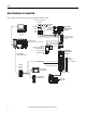
Chapter 1 Prepare the Kinetix 5500 Drive Hardware Connect the Kinetix 5500 Drive to the EtherNet/IP Network Ethernet connections are made at the PORT 1 and PORT 2 connectors. The Kinetix 5500 drives include two RJ45 connectors to support linear and ring topologies when multiple standalone drives are present. Kinetix 5500 Servo Drive (single, standalone) Kinetix 5500 Servo Drives (multiple, standalone) 1585J-M8CBJM-OM3 0.3 m (1.0 ft) Ethernet cable for drive-to-drive connections.
Prepare the Kinetix 5500 Drive Hardware Chapter 1 Assign an IP Address to the Kinetix 5500 Drive You can assign an IP address to the Kinetix 5500 drive manually via the drive keypad or dynamically via a DHCP-enabled server. Because this publication describes tasks intended to be completed on a private network, you assign an IP address. The Kinetix 5500 drive has two status indicators and an LCD status display.
Chapter 1 Prepare the Kinetix 5500 Drive Hardware Notes: 30 Rockwell Automation Publication IASIMP-QS035A-EN-P - December 2012
Chapter 2 Add a Kinetix 5500 Drive to a Logix Designer Application In this chapter, you add the Kinetix 5500 servo drive to your Logix Designer application project, download the project to the Logix5000 controller, and verify communication between drive and motor by applying power and testing an axis. Before You Begin Complete wiring the connector plugs, connecting the Ethernet cables, and configuring the IP address for your Kinetix 5500 drive (refer to Chapter 1).
Chapter 2 Add a Kinetix 5500 Drive to a Logix Designer Application Follow These Steps Apply Power to the Kinetix 5500 Drive L3 ove Rem DC For Only Bus Add the Kinetix 5500 Drive to the Logix Designer Project L2 L1 page 33 Configure the Motion Group page 37 page 40 Test and Tune the Axis page 41 Configure Axis Properties page 38 32 Rockwell Automation Publication IASIMP-QS035A-EN-P - December 2012
Add a Kinetix 5500 Drive to a Logix Designer Application Chapter 2 Add the Kinetix 5500 Drive to the Logix Designer Project IMPORTANT To configure Kinetix 5500 drives (catalog numbers 2198-Hxxx-ERS) you must be using Logix Designer Application, version 21.00 or later. 1. Verify that power is not applied at the mains input power (IPD) connector or the 24V input power (CP) connector. 2.
Chapter 2 Add a Kinetix 5500 Drive to a Logix Designer Application 7. Configure the new drive. a. Type the drive Name. b. Select an Ethernet Address option. In this example, the Private Network address is selected. c. Enter the address of your EtherNet/IP module. In this example, the last octet of the address is 1. The IP address must match the IP address configured on page 29. 8. Click OK to close the New Module dialog box.
Add a Kinetix 5500 Drive to a Logix Designer Application Chapter 2 13. Type the axis Name. AXIS_CIP_DRIVE is the default Data Type. 14. Click Create. The axis (Axis_1 in this example) appears in the Controller Organizer under Motion Groups>Ungrouped Axes and is assigned as Axis 1 on the Associated Axes tab. 15. Click Apply. 16. Click the Power tab.
Chapter 2 Add a Kinetix 5500 Drive to a Logix Designer Application 17. From the pull-down menus, choose the power options appropriate for your actual hardware configuration. Attribute Menu Description Voltage • 400-480 VAC • 200-240 VAC AC input voltage class. AC Input Phasing • Three Phase • Single Phase AC input phase. Kinetix 5500 drives with singlephase operation are limited to 2198-H003-ERS, 2198-H008-ERS, and 2198-H015-ERS.
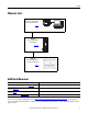
Add a Kinetix 5500 Drive to a Logix Designer Application Chapter 2 Configure the Motion Group Follow these steps to configure the motion group. 1. In the Controller Organizer, right-click Motion Groups and choose New Motion Group. The New Tag dialog box opens. 2. Type the new motion group Name. 3. Click Create. Your new motion group appears in the Controller Organizer under the Motion Groups folder. 4. Right-click the new motion group and choose Properties. The Motion Group Properties dialog box opens.
Chapter 2 Add a Kinetix 5500 Drive to a Logix Designer Application Configure Axis Properties Follow these steps to configure servo motor axis properties. 1. In the Controller Organizer, right-click an axis and choose Properties. 2. Select the General category. The General and Associated Module dialog box opens. 3. From the General pull-down menus, change configuration settings as needed for your application. 4. From the Associated Module>Module pull-down menu, choose your Kinetix 5500 drive.
Add a Kinetix 5500 Drive to a Logix Designer Application Chapter 2 The Motor Device Specification dialog box opens. 7. From the Data Source pull-down menu, choose Catalog Number. 8. Click Change Catalog. The Change Catalog Number dialog box opens. 9. Select the motor catalog number appropriate for your application. To verify the motor catalog number, refer to the motor name plate. 10. Click OK to close the Change Catalog Number dialog box. 11. Click Apply.
Chapter 2 Add a Kinetix 5500 Drive to a Logix Designer Application Apply Power to the Kinetix 5500 Drive This procedure assumes that you have wired and configured your Kinetix 5500 system and Logix5000 controller. SHOCK HAZARD: To avoid hazard of electrical shock, perform all mounting and wiring of the Bulletin 2198 servo drives prior to applying power. Once power is applied, connector terminals may have voltage present even when not in use. Follow these steps to apply power to the Kinetix 5500 system.
Add a Kinetix 5500 Drive to a Logix Designer Application Chapter 2 Test and Tune the Axis IMPORTANT Before proceeding with testing and tuning your axes, verify that the MOD and NET status indicators are operating as described in the Kinetix 5500 Servo Drives User Manual, publication 2198-UM001. For help using the Logix Designer application as it applies to testing and tuning your axes with ControlLogix® EtherNet/IP modules or CompactLogix 5370 controllers, refer to Additional Resources on page 9.
Chapter 2 Add a Kinetix 5500 Drive to a Logix Designer Application 4. In the Test Distance field, type 2.0 as the number of revolutions for the test. Test Description Marker Verifies marker detection capability as you rotate the motor shaft. Motor Feedback Verifies feedback connections are wired correctly as you rotate the motor shaft. Motor and Feedback Verifies motor power and feedback connections are wired correctly as you command the motor to rotate. 5.
Add a Kinetix 5500 Drive to a Logix Designer Application Chapter 2 Tune the Axes Follow these steps to tune the axes. 1. Verify that the load is still removed from the axis being tuned. ATTENTION: To reduce the possibility of unpredictable motor response, tune your motor with the load removed first, then reattach the load and perform the tuning procedure again to provide an accurate operational response. 2. Click the Autotune category. 3. Type values for Travel Limit and Speed.
Chapter 2 Add a Kinetix 5500 Drive to a Logix Designer Application The Logix Designer - Autotune dialog box opens. When the test completes, the Test State changes from Executing to Success. Tuned values populate the Loop and Load parameter tables. Actual bandwidth values (Hz) depend on your application and may require adjustment once motor and load are connected. 7. Click Accept Tuned Values. 8. Click OK to close the Logix Designer - Autotune dialog box. 9.
Index Numerics 24V input power connector wiring 19 A E EMC motor ground termination 26 Ethernet cables 11 EtherNet/IP network connect drive 28 applying power 40 associated axes tab 34 B BC connector wiring 24 bus regulator 36 C cables catalog numbers 22 Ethernet 11 shield clamp 26 SpeedTec DIN 11 catalog numbers motor cables 22 clamp 26 clearance requirements 14 configuring hookup test 41 module properties 34, 35 motion group 37 motor test 41 tune 43 servo motor axis general category 38 motor category
Index motion group 37 motors brake connector wiring 24 Bulletin VPL 11 cable catalog numbers 22 category 39 feedback connector wiring 25 ground termination 26 power connector wiring 23 shield clamp wiring 26 testing 41 tuning 41 mounting your drive clearance requirements 14 dimensions 15 hole patterns 16 zero-stack tab and cutout 13 MP connector wiring 23 N T testing axes hookup test 41 tuning axes autotune category 43 W where to start 9 wiring BC connector 24 CP connector 19 guidelines 19 interconnect
Rockwell Automation Support Rockwell Automation provides technical information on the Web to assist you in using its products. At http://www.rockwellautomation.com/support/, you can find technical manuals, a knowledge base of FAQs, technical and application notes, sample code and links to software service packs, and a MySupport feature that you can customize to make the best use of these tools.