Quick Start Logix5000 Control Systems: Connect ArmorBlock I/O Modules over an Ethernet Network Logix5000 Controllers, 1732E ArmorBlock I/O Modules
Important User Information Read this document and the documents listed in the additional resources section about installation, configuration, and operation of this equipment before you install, configure, operate, or maintain this product. Users are required to familiarize themselves with installation and wiring instructions in addition to requirements of all applicable codes, laws, and standards.
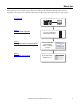
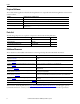
Where to Start This quick start provides examples and procedures for including 1732E ArmorBlock® EtherNet/IP modules in a Logix5000™ control system over an EtherNet/IP network. The figure below describes the tasks you must complete. Prerequisite Tasks Logix5565 RUN EtherNet/IP I/O RS232 OK Logix5565 REM Chapter 1 Install Your ArmorBlock I/O Module PROG 1756-EN2T BAT RUN LINK 1 LINK 2 MOD NET 0 Prepare the 1732E ArmorBlock EtherNet/ IP Module Hardware.
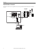
Where to Start How the Hardware Is Connected This quick start demonstrates the Logix5000 control system using ArmorBlock EtherNet/IP modules on an Ethernet network. 1732E ArmorBlock Ethernet Modules 192.168.1.x LINK 1 Slot 0 1 2 3 LINK 2 MOD NET 0 Logix5565 RUN 15 EtherNet/IP I/O RS232 OK BAT RUN PROG 1756-EN2T 24V DC Logix5565 Local Chassis REM 1 14 2 13 3 12 4 11 5 6 10 9 7 8 X10 P W R X100 Logix5565 Controller (Slot 1) 1756-EN2T 192.168.1.20 (Slot 3) Switch 192.168.1.
Table of Contents Preface About This Publication. . . . . . . . . . . . . . . . . . . . . . . . . . . . . . . . . . . . . . . . . . . . . 7 Prerequisite Tasks . . . . . . . . . . . . . . . . . . . . . . . . . . . . . . . . . . . . . . . . . . . . . . . . . . 7 Other Logix5000 Control System Quick Starts . . . . . . . . . . . . . . . . . . . . . . . 7 Required Software . . . . . . . . . . . . . . . . . . . . . . . . . . . . . . . . . . . . . . . . . . . . . . . . . 8 Parts List . . . . . . . . . . . . . . .
Table of Contents Notes: 6 Rockwell Automation Publication IASIMP-QS039A-EN-P - July 2013
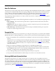
Preface About This Publication This quick start provides examples and procedures for including 1732E ArmorBlock EtherNet/IP modules in a Logix5000 control system over an EtherNet/IP network (star topology configuration). This document does not describe how to use the I/O modules in a device-level ring (DLR) or linear topology. For information on using modules in a DLR or linear topology, see the EtherNet/IP Embedded Switch Technology Application Guide, publication ENET-AP005.
Preface Required Software The module and the applications described in this publication are compatible with the following firmware revisions and software versions. Product Firmware Revision / Software Version 1756-EN2T, 1756-EN2TR, 1756-EN3TR 3.000 revision when using RSLogix 5000 version 20 or Studio 5000 Logix Designer™ version 21 or later RSLogix 5000 software 20.00.00 or later RSLinx software 2.56.
Chapter 1 Install Your ArmorBlock I/O Module This chapter shows you how to install and wire the 1732E ArmorBlock EtherNet/IP module. Before You Begin Perform the prerequisite tasks outlined on page 7. What You Need The only tools required are a flat or Phillips-head screwdriver and a drill. Follow These Steps Complete these steps to install your ArmorBlock EtherNet/IP module.
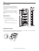
Chapter 1 Mount the Module Two holes are used to mount the module directly to a panel or machine. Mounting holes accommodate #6 (M3) pan-head screws. The torque specification is 0.68 N•m (6 lb•in). 65.0 (2.56) To mount the module on a wall or panel, use the screw holes provided in the module. Refer to the drilling dimensions illustration to guide you in mounting the module. LINK 1 LINK 2 NET MOD 179.0 (7.05) Mounting Dimensions 43.3 (1.70) 26.5 (1.
Chapter 1 Wire the Module Connect the I/O, network and auxiliary cables to the module. The ArmorBlock EtherNet/IP family has 5-pin micro-style connectors. Caps are provided to cover the unused connectors on your module. Connect the quick-disconnect cord sets you selected for your module to the appropriate ports. Functional Earth Functional Earth This screw grounds the I/O block EtherNet/IP communication circuitry that is designed to reduce the effect of noise on the network.
Chapter 1 Mini-style 4-pin Input Male Receptacle (Auxiliary Power) 4 2 3 1 (View into receptacle) Pin 1 Output power + Pin 2 Sensor /MDL power+ Pin 3 Sensor/MDL powerPin 4 Output power- Set the Network Address The module ships with the rotary switches set to 999 and DHCP enabled. To change the network address, you can do one of the following: • adjust the switch on the front of the module. • use a Dynamic Host Configuration Protocol (DHCP) server, such as Rockwell Automation BOOTP/DHCP.
Chapter 1 Use the Rockwell Automation BOOTP/DHCP Utility The Rockwell Automation BOOTP/DHCP utility is a standalone program that incorporates the functionality of standard BOOTP/DHCP software with a user-friendly graphical interface. The BOOTP/DHCP utility is in the Utils directory on the RSLogix 5000 installation CD. The module must have DHCP enabled (factory default and the network address switches set to an illegal value) to use the utility.
Chapter 1 3. Enter the IP Address you want to assign to the device and click OK. The device is added to the Relation List, displaying the Ethernet Address (MAC) and corresponding IP Address, Hostname and Description (if applicable). When the IP address assignment is made, the address appears in the IP Address column in the Request History section. 4. To assign this configuration to the device, select the device in the Relation List panel and click Disable BOOTP/ DHCP.
Chapter 2 Use RSLogix 5000 Software to Configure the Module This chapter shows you how to create an RSLogix 5000 project. Before You Begin You must complete these tasks before proceeding: • The tasks described on page 7. • Tasks described in Chapter 1 on page 9. What You Need You need RSLogix 5000 software to complete the tasks in this chapter. Follow These Steps Follow these steps to create an RSLogix 5000 project.
Chapter 2 Add the Local EtherNet/IP Bridge to the I/O Configuration 1. Open the RSLogix 5000 software. I/O configuration can be performed offline. 2. To add the EtherNet/IP bridge to your RSLogix 5000 project, right-click 1756 Backplane and choose New Module. The Select Module dialog box appears.
Chapter 2 3. Select the 1756-EN2T EtherNet/IP bridge and click OK. The New Module dialog box opens. 4. Configure the module. a. Name the bridge. b. Enter the IP address. c. Select slot 3 for the EtherNet/IP bridge. d. Make sure the Minor Revision number matches your module revision number. e. Choose an Electronic Keying method. f. Click OK. 5. Add the I/O module as a child of the 1756-EN2T module. The New Module dialog box opens.
Chapter 2 Configure the Bridge Module 1. From the Select Module Type dialog box, select the 1732E-OB16M12R module and click Create. To look for the 1732E-OB16M12R module in the list, you can type the catalog number in the search box or use the filters. The New Module dialog box appears.
Chapter 2 2. Enter the Module Properties information as shown. 3. Click OK. Add Ladder Logic to Test the Lights on the 1732E-OB16MR Module 1. In the controller organizer of the RSLogix 5000 software, expand to show: Tasks > MainTask > MainProgram. 2. Double-click MainRoutine. A blank routine opens. 3. Add a new rung to the routine.
Chapter 2 4. From the Element Toolbar, drag and drop an Examine On element and an Output Energize element onto the rung. 5. Double-click ? in the Examine On element. 6. Type “PB” for button. 7. Press Enter. 8. Right-click PB and choose New “PB”. The New Tag dialog box appears.
Chapter 2 9. Click Create and Close to use the default values. 10. Double-click ? in the Output Energize element. 11. Name the Output Energize element OB16_Light. IMPORTANT Do not use spaces in the tag name. Use underscores (__) instead.
Chapter 2 12. Right-click the OB16_Light tag and choose New “OB16_Light”. OB16_Light is an alias tag for the I/O point tag name. With an alias tag, you can assign a simple name to a physical I/O point address. 13. From the Type pull-down menu, choose Alias. 14. Browse to the 1732E-OB16M12R digital output module and select any bit. For this example we are using TEST_OB16M12R:O.Data [0]. 15. Click Create and Close. This graphic shows the rung created with these steps.
Chapter 2 Download the Project to Your Logix5000 Controller After you configure your module, download it to the owner-controller. The download transfers the entire program to the controller, overwriting any existing program. 1. Save your changes. 2. Move the controller’s switch to Program. RUN REM PROG 3. Click the Controller Status icon and choose Download. The Download dialog box appears. 4. Click Download. This completes the download process.
Chapter 2 Test the 1732E-OB16M12R Output Module’s Light 1. Move the controller’s mode switch to the RUN position. 2. Open the Main Routine of the project to find the ladder logic written earlier. 3. Select the PB and press Ctrl+T. This toggles the state from 0 to 1 (off to on). 4. Verify that the light on the distributed output module turns on. 5. Press Ctrl+T to toggle the state 1 back to 0 (off ). 6. Choose Go Offline.
Chapter 3 Embedded Web Server Introduction Rockwell Automation offers enhanced 1732E ArmorBlock for your EtherNet/IP control systems so you can monitor data remotely via web pages. This chapter shows how you can use the web server. The module provides access to internal and network diagnostics. This access opens up different, remote access applications to control systems. Use the ArmorBlock I/O web browser to remotely access module data.
Chapter 3 Access the Home Page of the Web Server From your web browser, enter the IP address of the 1732E ArmorBlock module in the Address field and press Enter. The home page of the module is displayed. Log On to the Web Server Many of the features of the 1732E ArmorBlock I/O require you to log on with appropriate access. If you select a feature, such as Configuration, the module prompts you to enter your user name and password.
Chapter 3 Navigating the Web Server Pages You navigate the web server pages by using the navigation panel on the left of the screen. You can also use the tabs across the top to navigate the sections within folders.
Chapter 3 Notes: 28 Rockwell Automation Publication IASIMP-QS039A-EN-P - July 2013
Rockwell Automation Support Rockwell Automation provides technical information on the Web to assist you in using its products. At http://www.rockwellautomation.com/support you can find technical and application notes, sample code, and links to software service packs. You can also visit our Support Center at https://rockwellautomation.custhelp.com/ for software updates, support chats and forums, technical information, FAQs, and to sign up for product notification updates.