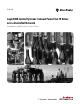
Quick Start Logix5000 Control Systems: Connect PowerFlex 70 Drives over a DeviceNet Network Catalog Numbers Logix5000 Controllers, PowerFlex 70 Drives
Important User Information Solid-state equipment has operational characteristics differing from those of electromechanical equipment. Safety Guidelines for the Application, Installation and Maintenance of Solid State Controls (publication SGI-1.1 available from your local Rockwell Automation sales office or online at http://www.rockwellautomation.com/literature/) describes some important differences between solid-state equipment and hard-wired electromechanical devices.
Table of Contents Preface About This Publication Before Using This Publication . . . . . . . . . . . . . . . . . . . . . . . . . . . . . . . . . . . . . . 5 Other Logix5000 Control System Quick Starts . . . . . . . . . . . . . . . . . . . . . . . 8 Where to Start . . . . . . . . . . . . . . . . . . . . . . . . . . . . . . . . . . . . . . . . . . . . . . . . . . . . . 9 How Hardware is Connected . . . . . . . . . . . . . . . . . . . . . . . . . . . . . . . . . . . . . 10 Required Software . . . . . . . . .
Table of Contents Notes: 4 Rockwell Automation Publication IASIMP-QS030A-EN-P - July 2012
Preface About This Publication This quick start provides examples and procedures for including PowerFlex® 70 drives in a Logix5000 controllers control system over a DeviceNet network. The programming examples are not complex, and offer easy solutions to verify that devices are functioning and communicating properly. IMPORTANT This publication describes example tasks you complete when using PowerFlex 70 drives on a DeviceNet network.
Preface This table describes the tasks you must complete before using this publication. Table 1 - Required Tasks to Complete before Using This Quick Start Task Description Prepare the Logix5000 Assembling the control system and connecting to the DeviceNet network. At minimum, your system must control system include a controller, DeviceNet scanner module to access the DeviceNet network and the components required hardware to install a DeviceNet network.
Preface Table 1 - Required Tasks to Complete before Using This Quick Start Task Description Configure the network Completing tasks associated with configuring the DeviceNet network with RSNetWorx for DeviceNet software, such as setting the node address for the DeviceNet scanner module your controller uses to access the DeviceNet network.
Preface Other Logix5000 Control System Quick Starts This quick start describes how to use a single component-type over a single network in a Logix5000 control system. Typically, though, a Logix5000 control system includes more than the controller, communication module, and a single component over a single network.
Preface Where to Start Required Tasks Described in the appropriate Logix5000 controller quick start 1. Prepare the Controller Hardware 2. Prepare the Computer 3. Configure the Network 4.
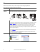
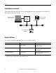
Preface How Hardware is Connected This quick start demonstrates the following Logix5000 control system that uses PowerFlex 70 drives on a DeviceNet network. Logix5000 Controller with DeviceNet Scanner Module Computer Connected to Logix5000 Controller PowerFlex 70 Drive with 20-COMM-D Adapter DeviceNet Power Supply 1606-XLDNET8 Required Software To complete examples in this quick start, you need this software. Software Required Software Version, min Required for This Task RSLogix 5000 20.00.
Preface Parts List You need these parts to use this publication. Quantity Cat. No.
Preface Notes: 12 Rockwell Automation Publication IASIMP-QS030A-EN-P - July 2012
Chapter 1 Prepare the PowerFlex 70 Drive Hardware In this chapter, you learn how to complete the following tasks: • Mount and wire power to a PowerFlex 70 drive. • Set the DeviceNet communication card’s operation mode, node address, and communication rate. • Connect the communication card to the drive. • Connect the communication card to the network.
Chapter 1 Prepare the PowerFlex 70 Drive Hardware What You Need This table lists the products you need to complete the tasks described in this chapter. Quantity Cat. No.
Prepare the PowerFlex 70 Drive Hardware Chapter 1 Mount the Drive For the purpose of this quick start, the PowerFlex 70 drive can be propped in a safe and convenient location. For complete mounting instructions, see the PowerFlex 70 Drive User Manual, publication 20A-UM001. Wire Power to the Drive WARNING: Verify that all incoming power is turned off before wiring power. Do not apply incoming power before connecting the DeviceNet adapter to the drive. 1. Loosen the screw and remove the cover. 2.
Chapter 1 Prepare the PowerFlex 70 Drive Hardware 4. Loosen the screws and slide the metal plate out of the drive. The 20A-B4P2A0AYNNNC0 drive can use any of the following inputs: • 208V AC three phase • 230V AC three phase In this quick start, you use 208V AC/240V AC three phase. 5. Connect the AC power conductors to the drive terminals as described in the following table and tighten the screws.
Prepare the PowerFlex 70 Drive Hardware Chapter 1 Set the Node Address and Communication Rate 1. Use a small screwdriver to rotate the switches to the desired value to set the adapter’s node address. 2 4 0 9 This quick start uses a node address 1. 3 4 1 5 6 8 2. Use a small screwdriver in the same manner to set the DeviceNet adapter’s communication rate. 2 3 1 7 Tens Digit 0 5 9 6 8 7 Ones Digit 500K PGM 250K 125K This quick start uses 125 Kbps.
Chapter 1 Prepare the PowerFlex 70 Drive Hardware Connect the DeviceNet Adapter to the Drive WARNING: Verify that all incoming power is turned off before connecting the adapter to the drive. 1. Connect the Internal Interface cable to the DPI connector on the drive and then to the DPI connector on the adapter. DPI Connectors Internal Interface Cable 2. Fold the cable behind the adapter without creasing it and mount the adapter on the drive by using four captive screws.
Prepare the PowerFlex 70 Drive Hardware Chapter 1 Connect the Drive to the DeviceNet Network 1. Remove a knockout from the bottom plate on the drive. A hole is created at the bottom of the drive through which you can route a connector cable. Knockout 2. Connect the 1799-DNC5MMS 5-pin linear to micro male adapter to the female end of the 1485KP1F5-R5 KwikLink right-angle micro male to micro female connector cable. 3.
Chapter 1 Prepare the PowerFlex 70 Drive Hardware 4. Place the cover on the drive and tighten the screw. 5. Connect the drive to the DeviceNet network. 6. Apply power to the drive.
Chapter 2 Create DeviceNet Network Software Files In this chapter, you complete the following tasks: • Register an EDS file in RSNetWorx for DeviceNet software • Set the DeviceNet scanner module’s node address • Create a DeviceNet configuration file • Associate a DeviceNet configuration file with an RSLogix 5000 project • Create a DeviceNet scanlist IMPORTANT Multiple Logix5000 control systems can use PowerFlex 70 drives over a DeviceNet network.
Chapter 2 • Create DeviceNet Network Software Files These tasks described in Chapter 1, Prepare the PowerFlex 70 Drive Hardware on page 13: – Mount the Drive – Wire Power to the Drive – Set the Node Address and Communication Rate – Connect the DeviceNet Adapter to the Drive – Connect the Drive to the DeviceNet Network What You Need You need RSNetWorx for DeviceNet software to complete the tasks in this chapter.
Create DeviceNet Network Software Files Chapter 2 Register an EDS File - Optional You might need to register a device for use in RSNetWorx for DeviceNet software so the software recognizes the device and uses it appropriately. You register an electronic data sheet (EDS) file in the software. If you do not need to register an EDS file in RSNetWorx for DeviceNet software, skip to Set the 1769-SDN Scanner Module’s Node Address on page 26. 1.
Chapter 2 Create DeviceNet Network Software Files 6. When the EDS dialog box appears, click Next. 7. Verify that Register an EDS file(s). is checked and click Next. 8. Browse to the EDS file and click Next.
Create DeviceNet Network Software Files Chapter 2 9. When the EDS File Installation Test Results screen appears, click Next. 10. Select the graph image for the device you want to register and click Next. 11. Select the device you want to register and click Next. 12. Click Finish when the registration is successful.
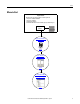
Chapter 2 Create DeviceNet Network Software Files Set the 1769-SDN Scanner Module’s Node Address This quick start describes how to use a PowerFlex 70 drive in a CompactLogix 5370 L3 control system over a DeviceNet network. The computer is connected to the controller via an EtherNet/IP network, and the controller accesses the drive on the DeviceNet network via a 1769-SDN scanner module installed in a local expansion module slot.
Create DeviceNet Network Software Files Chapter 2 3. From the Tools menu, choose Node Commissioning. 4. Click Browse. When the Device Selection dialog box appears, browse to the 1769-SDN scanner module over an EtherNet/IP network or USB connection. This example uses an EtherNet/IP network connection. 5. Under the AB_ETHIP-1 driver, expand the path to the 1769-SDN scanner module as shown in the example graphic. 6. Click OK.
Chapter 2 Create DeviceNet Network Software Files 7. If you receive a linking device warning, click Yes. The Node Commissioning dialog box is populated with the 1769-SDN module’s current settings. 8. Enter a node address of 1 for the 1769-SDN scanner module and click Apply. The Address is applied and is confirmed in the Messages box. 9. Record the node address. 10. Click Close.
Create DeviceNet Network Software Files Chapter 2 Create a DeviceNet Configuration File 1. From the File menu, choose New. 2. Click Who Active to go online. 3. Expand the networks to the appropriate DeviceNet network. In this example, the network is Port 2, DeviceNet.
Chapter 2 Create DeviceNet Network Software Files 4. Record the following information about the scanner module: – – Slot number in the CompactBus = 1 DeviceNet network node number = 0 Slot number = 1 DeviceNet network node number = 0 5. Click OK. 6. Click OK when the alert about uploading or downloading device information appears. RSNetWorx for DeviceNet software browses the network and shows the scanner module at DeviceNet network node 0 and the drive at node 1.
Create DeviceNet Network Software Files Chapter 2 7. Right-click the scanner module and choose Properties. 8. Click the Module tab. 9. Click Download. All configuration is cleared from the scanner module, and the software is synchronized with the module. IMPORTANT If you receive a fault message on your PowerFlex 70 drive, press Rockwell Automation Publication IASIMP-QS030A-EN-P - July 2012 on the keypad to clear the fault.
Chapter 2 Create DeviceNet Network Software Files 10. From the Platform pull-down menu, choose CompactLogix. 11. Enter the slot number of the 1769-SDN scanner module. 12. Click OK. 13. Save the file and record the file name and path. This quick start uses the example file name DeviceNet.dnt. 14. Close RSNetWorx for DeviceNet software.
Create DeviceNet Network Software Files Chapter 2 Associate the DeviceNet Configuration File with an RSLogix 5000 Project You must associate the DeviceNet network configuration file with your RSLogix 5000 project. TIP If you already created an RSLogix 5000 project for your Logix5000 controller, as described in Logix5000 controller quick starts, go to step 5 on page 34. 1. Verify the controller’s mode switch is in the PROG position. RUN REM 2. Open a new RSLogix 5000 project. PROG 3.
Chapter 2 Create DeviceNet Network Software Files 5. Configure the scanner module’s parameters on the RSNetWorx tab to associate the RSLogix 5000 project with the DeviceNet configuration file created in Create a DeviceNet Configuration File on page 29. IMPORTANT If you skipped step 1…step 4 because you already created an RSLogix 5000 project for your Logix5000 controller, verify that the project is open and you have accessed the scanner module’s RSNetWorx configuration tab. a. On the click Browse. b.
Create DeviceNet Network Software Files Chapter 2 Create a DeviceNet Scanlist 1. Verify that your RSLogix 5000 project that is used with this quick start is open and online. 2. In your RSLogix 5000 project, right-click the scanner module and choose properties. 3. On the RSNetWorx tab, click the Launch RSNetWorx for DeviceNet icon. If the project is not associated with the configuration file, use the Browse function to associate them with each other. 4. Click the Launch RSNetWorx for DeviceNet icon.
Chapter 2 Create DeviceNet Network Software Files 7. Right-click the PowerFlex 70 drive and choose Download to Device. 8. When prompted to continue configuration download, click Yes. The configuration downloads to the PowerFlex 70 drive. 9. Right-click the PowerFlex 70 drive and choose Properties.
Create DeviceNet Network Software Files Chapter 2 10. If your drive has not been previously used, skip to step 12. 11. If your PowerFlex 70 drive has been used previously, reset it to factory defaults. a. Click the Parameters tab. b. From the Parameter 197, Reset to Defalts pull-down menu, choose Factory. c. Click Apply. Optional Selection 12. Use the pull-down menus to change the following parameters.
Chapter 2 Create DeviceNet Network Software Files 14. When prompted to download the configuration and update the device, click Yes. 15. Right-click the 1769-SDN scanner module and choose Properties. 16. Click the Scanlist tab on the 1769-SDN Scanner Module dialog box. 17. When prompted to upload or download the configuration, click Upload.
Create DeviceNet Network Software Files Chapter 2 When the upload is complete, the Scanlist tab appears. 18. Verify that Automap on Add is checked. 19. Click the right arrow to move the PowerFlex 70 drive to the Scanlist. 20. Click OK. 21. When prompted to download changes, click Yes. 22. Click OK. 23. Save the file and close RSNetWorx for DeviceNet software.
Chapter 2 Create DeviceNet Network Software Files Notes: 40 Rockwell Automation Publication IASIMP-QS030A-EN-P - July 2012
Chapter 3 Use a PowerFlex 70 Drive in an RSLogix 5000 Project In this chapter, you complete the following tasks: • Create DeviceNet tags with the DeviceNet Tag Generator tool • Download the updated RSLogix 5000 project to your controller • Test the drive tags IMPORTANT Multiple Logix5000 control systems can use PowerFlex 70 drives over a DeviceNet network.
Chapter 3 Use a PowerFlex 70 Drive in an RSLogix 5000 Project Before You Begin Before you begin, you must complete these tasks: • These tasks described in Before Using This Publication on page 5: – – – – • These tasks described in Chapter 1, Prepare the PowerFlex 70 Drive Hardware on page 13: – – – – – • Mount the Drive Wire Power to the Drive Set the Node Address and Communication Rate Connect the DeviceNet Adapter to the Drive Connect the Drive to the DeviceNet Network These tasks described in Cha
Use a PowerFlex 70 Drive in an RSLogix 5000 Project Chapter 3 What You Need You need the following software to complete the tasks in this chapter: • DeviceNet Tag Generator tool in RSLogix 5000 software • RSLogix 5000 software Follow These Steps Create DeviceNet Tags page 44 Download the Project page 44 Test the PowerFlex 70 Drive Tags page 48 Rockwell Automation Publication IASIMP-QS030A-EN-P - July 2012 43
Chapter 3 Use a PowerFlex 70 Drive in an RSLogix 5000 Project Create DeviceNet Tags IMPORTANT Before running the DeviceNet Tag Generator, verify the following: • RSNetWorx for DeviceNet software is closed. • RSLogix 5000 project is open and offline. 1. Launch the DeviceNet Tag Generator tool. 2. Select your RSLogix 5000 project and click Select Scanner. 3. Select the 1769-SDN scanner module that scans the network where the device is located and click Select RSNetWorx Project.
Use a PowerFlex 70 Drive in an RSLogix 5000 Project Chapter 3 4. Select the main DeviceNet configuration file and click Select Scanner Node. 5. Select the node of the DeviceNet scanner module and click Generate Tags. 6. Click Generate Tags.
Chapter 3 Use a PowerFlex 70 Drive in an RSLogix 5000 Project 7. When prompted to continue, click Yes. When tag generation is complete, the text log appears. 8. Close the DeviceNet Tag Generator. The DeviceNet Tag Generator created new programs and tags that were added to the controller organizer in your RSLogix 5000 project.
Use a PowerFlex 70 Drive in an RSLogix 5000 Project Chapter 3 Download the Project 1. Save your RSLogix 5000 project. 2. Verify that the controller’s mode switch is in the PROG position. RUN REM PROG 3. Click the Controller Status icon and choose Download. 4. On the Download dialog box, click Download. The project downloads to the controller. IMPORTANT If you receive a fault message on your PowerFlex 70 drive, press on the keypad to clear the fault.
Chapter 3 Use a PowerFlex 70 Drive in an RSLogix 5000 Project Test the PowerFlex 70 Drive Tags 1. Move the controller’s mode switch to the RUN position. RUN REM PROG 2. In the configuration tree, doubleclick Controller Tags. 3. Change the O.CommandRegister.Run tag to 1. The 1769-SDN scanner module transitions to Run mode. 4. If you receive a fault message on your PowerFlex 70 drive, press on the keypad to clear the fault.
Use a PowerFlex 70 Drive in an RSLogix 5000 Project Chapter 3 5. Change the Local_DeviceNet_scanner_N01_ POL_O.Reference tag to 15000. This value is the speed to which your drive accelerates. 6. Change the Local_DeviceNet_scanner_N01_ POL_O.Start tag to 1. The display on the drive registers the speed increase in Hertz until the value entered at the reference tag is reached. 7. Change the O.Start tag back to 0.
Chapter 3 Use a PowerFlex 70 Drive in an RSLogix 5000 Project 8. Change the O.Stop tag to 1. The display on the drive shows a speed decrease until the drive reaches 0.00 Hz. 9. Change the Stop tag back to 0. 10. Select Go Offline. By starting and stopping the drive, you verified the following: • The controller is correctly communicating with the drive. • The drive can receive simple commands.
Index Numerics 1485K-P1F5-R5 KwikLink right-angle micro male to micro female connector cable 11, 14 1769-SDN scanner module 26-28 1785P-P1E4-R5 Kwiklink sealed micro connector 11, 14 1799-DNC5MMS 5-pin linear to micro male adapter 11, 14 20A-B4P2A0AYNNNC0 PowerFlex 70 drive 11, 14 20-COMM-D DeviceNet adapter 11, 14 configuration file 29-32 configure network 7 configure scanlist 35-39 connect 20A-B4P2A0AYNNNC0 PowerFlex 70 drive to network 19 create tags 44-46 set communication rate on 20-COMM-D DeviceNet a
Index P prerequisite tasks 6-7 Q quick starts for devices in other Logix5000 control systems 8 R requirements prerequisite tasks 6-7 software 10, 22, 43 RSLogix 5000 software 7, 47-50 DeviceNet Tag Generator tool 43, 44-46 requirements 10 use tags 48 RSNetWorx for DeviceNet software 7, 35-39 configuration file 29-32 configure scanlist 35-39 register an EDS file 23-25 requirements 10 set node address on 1769-SDN scanner module 26-28 52 Rockwell Automation Publication IASIMP-QS030A-EN-P - July 2012 S so
Rockwell Automation Support Rockwell Automation provides technical information on the Web to assist you in using its products. At http://www.rockwellautomation.com/support/, you can find technical manuals, a knowledge base of FAQs, technical and application notes, sample code and links to software service packs, and a MySupport feature that you can customize to make the best use of these tools.