
Quick Start Owner's manual


Rockwell Automation Publication IASIMP-QS032A-EN-P - March 2012 17
Prepare the Kinetix 350 Drive Hardware Chapter 1
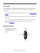
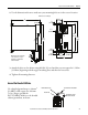
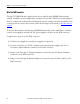
2. Use the dimensions shown to make sure your mounting holes are in the correct location.
3. Attach the drive to the cabinet using M4 (#6-32) steel machine screws torqued to 1.1 N
m
(9.8 lb
in) beginning with the upper mounting slots and then the lower slots.
4. Tighten all mounting fasteners.
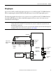
Ground the Kinetix 350 Drive
Use a braided ground strap or 4.0 mm
2
(12 AWG) solid copper wire 100 mm
(3.9 in.) long to ground the
2097-V31PR2-LM drive to the bonded
cabinet ground bus, as shown.
11.8
(0.46)
6.6
(0.26)
7.1
(0.28)
B
38.1
(1.5)
182
(7.18)
190
(7.50)
30.8
(1.21)
Ø 4.57
(0.18) 3x
A
238
(9.37)
9.7
(0.38)
5.0
(0.19)
238 mm
(9.37 in.)
Additional clearance below the
connector kit is necessary to
provide the recommended
cable bend radius.
Dimensions are in mm (in.)
Braided Ground Strap Bonded Cabinet Ground Bus
Ground Grid or Power
Distribution Ground
Ground Stud