Quick Start Logix5000 Control Systems: Connect Kinetix 350 Drives over an EtherNet/IP Network Catalog Numbers Logix5000 Controllers, Kinetix 350 Drives
Important User Information Solid-state equipment has operational characteristics differing from those of electromechanical equipment. Safety Guidelines for the Application, Installation and Maintenance of Solid State Controls (publication SGI-1.1 available from your local Rockwell Automation sales office or online at http://www.rockwellautomation.com/literature/) describes some important differences between solid-state equipment and hard-wired electromechanical devices.
Table of Contents Preface About This Publication . . . . . . . . . . . . . . . . . . . . . . . . . . . . . . . . . . . . . . . . . . . . 5 Before Using This Publication. . . . . . . . . . . . . . . . . . . . . . . . . . . . . . . . . . . . . . 5 Other Logix5000 Control System Quick Starts . . . . . . . . . . . . . . . . . . . . . . 8 Use Each Chapter . . . . . . . . . . . . . . . . . . . . . . . . . . . . . . . . . . . . . . . . . . . . . . . . . 8 Where to Start . . . . . . . . . . . . . . . . . . . . . .
Table of Contents Notes: 4 Rockwell Automation Publication IASIMP-QS032A-EN-P - March 2012
Preface About This Publication This quick start provides examples and procedures for integrating a Kinetix 350 drive into any Logix5000 controllers control system over an EtherNet/IP network. The programming examples are not complex, and offer easy solutions to verify that devices are functioning and communicating properly. IMPORTANT This publication describes basic example tasks you can complete when using a Kinetix 350 drive over an EtherNet/IP network.
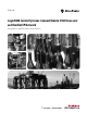
Preface Table 1 - Required Tasks to Complete before Using This Quick Start Task Description Prepare the Logix5000 Assemble the control system and connect to necessary communication networks. Some components, for control system example, the Logix5000 controller and system power supply, are required. Other components, for example, a hardware network communication module, are optional. These example graphics show the assembly of one Logix5000 controller.
Preface Table 1 - Required Tasks to Complete before Using This Quick Start Task Description Configure the networks Complete required tasks associated with the networks used in your application, such as assigning an IP address to the controller’s communication port or communication module in your Logix5000 control system. Create an RSLogix 5000 project Create a project to be used with your Logix5000 controller. A project includes all desired control system components and necessary programming.
Preface Other Logix5000 Control System Quick Starts This quick start describes how to use one device on one network in a Logix5000 control system. Typically, though, a Logix5000 control system includes more than the controller and one device on one network. For example, if a Logix5000 control system operates on an EtherNet/IP network, in addition to a controller, power supply, and communication modules, the system might use remote I/O modules, drives, and HMI terminals.
Preface Where to Start Prerequisite Tasks Described in Before Using This Publication on page 5. 1. Prepare the Logix5000 control system hardware 2. Prepare the computer 3. Configure the networks 4.
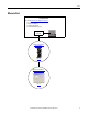
Preface How Hardware is Connected This graphic shows an example control system that uses a Kinetix 350 drive. Single-phase Input Power Logix5000 Controller PanelView Plus Terminal Computer with RSLogix 5000 Software Stratix 2000 Switch 1 P W R 2 3 Kinetix 350 Drive 4 5 1734 POINT I/O Modules AC Line Filter Shunt Resistor Terminal Expansion Block Motor Feedback Cable MP-Series Rotary Motor Required Software To complete examples in this quick start, you need RSLogix 5000 software.
Preface Parts List You need these parts to complete the tasks described in this quick start. Quantity Cat. No. Description 1 2097-V31PR2-LM Kinetix 350 Single Axis Ethernet/IP Servo Drive 1 MPL-A310P-MJ72AA MP-Series Low-inertia Servo Motor 1 The connectors required to 6-pin Safe Torque Off (STO) Connector use Kinetix 350 drives vary 6-pin Motor Power (MP) Connector by drive catalog number.
Preface Additional Resources Resource Description Kinetix 350 Single-axis EtherNet/IP Servo Drives User Manual, publication 2097-UM002 Describes how to install, wire, configure, operate, and troubleshoot your Kinetix 350 drive. Kinetix 350 Single-axis EtherNet/IP Servo Drives Installation Instructions, publication 2097-IN008 Describes how to install and wire your Kinetix 350 drive.
Chapter 1 Prepare the Kinetix 350 Drive Hardware In this chapter, you learn how to complete the following tasks: • Mount a 2097-V31PR2-LM drive. • Make multiple connections, for example, power, feedback and resistor connections to the drive. • Configure EtherNet/IP communication for the drive.
Chapter 1 Prepare the Kinetix 350 Drive Hardware What You Need This table lists the products you need to complete the tasks described in this chapter. Quantity Cat. No. Description 1 2097-V31PR2-LM Kinetix 350 Single Axis Ethernet/IP Servo Drive 1 MPL-A310P-MJ72AA MP-Series Low-inertia Servo Motor 1 The connectors required to 6-pin Safe Torque Off (STO) Connector use Kinetix 350 drives vary 6-pin Motor Power (MP) Connector by drive catalog number.
Prepare the Kinetix 350 Drive Hardware Chapter 1 Follow These Steps Wire the Input Power Connector Prepare the Panel page 16 page 23 Mount the Kinetix 350 Drive Wire the Motor Power Connector PE W W V V U page 17 U page 24 Ground the Kinetix 350 Drive Apply the Motor Cable Shield Clamp page 17 Wire the Motor Feedback Connector 1 2 3 4 5 6 STO Disable the Safe Torque-off Feature page 25 page 18 page 26 Pin 46 Pin 47 Pin 48 Pin 49 Pin 50 Wire the IOD Connector + - Pin 25 Pin 26 Pin 27
Chapter 1 Prepare the Kinetix 350 Drive Hardware Prepare the Panel You must install the 2097-V31PR2-LM drive on a grounded panel. This quick start assumes you installed a panel when you fulfilled the prerequisite task of installing the Logix5000 control system hardware: • If you have already installed a painted, grounded panel, move to section Mount the Kinetix 350 Drive. • If you have not already installed a painted, grounded panel, do so before proceeding to the next section.
Prepare the Kinetix 350 Drive Hardware Chapter 1 2. Use the dimensions shown to make sure your mounting holes are in the correct location. Dimensions are in mm (in.) A 5.0 (0.19) 7.1 (0.28) 30.8 (1.21) 9.7 (0.38) 182 (7.18) 238 mm (9.37 in.) 190 (7.50) 238 (9.37) 6.6 (0.26) 11.8 (0.46) Additional clearance below the connector kit is necessary to provide the recommended cable bend radius. 38.1 (1.5) Ø 4.57 (0.18) 3x B 3.
Chapter 1 Prepare the Kinetix 350 Drive Hardware Disable the Safe Torque-off Feature The safe torque-off feature is used in applications used in safety conditions. This feature safely removes power from the gate firing circuits of the drives output power devices (IGBTs). The feature is enabled by default when the Kinetix 350 drive ships from the factory. If your application, for example, the one used in this quick start, does not require the use of safety options, you disable the safe torque-off feature.
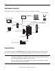
Prepare the Kinetix 350 Drive Hardware Chapter 1 Wiring Diagram You can wire 120V or 240V single-phase input power to your Kinetix 2097-V31PR2-LM drive. When completing the tasks described in this quick start, you use 120V single-phase power. The following graphic shows how to wire connectors on your Kinetix 2097-V31PR2-LM drive for 120V single-phase power. More detailed descriptions of how to wire each connector are included later in this chapter.
Chapter 1 Prepare the Kinetix 350 Drive Hardware Wire the IOD Connector The 2097-V31PR2-LM drive ships from the factory with the drive ENABLE functionality enabled. In addition to this configuration, you must wire the 2097-TB1 I/O terminal expansion block to complete the tasks described in this quick start, for example, the tasks described in Your control system can execute drive actions, such as the Hookup test described on Test the Axis on page 44.
Prepare the Kinetix 350 Drive Hardware Chapter 1 5. Connect a wire from a +24V DC terminal on the external power supply to pin 29 (ENABLE signal) on the IOD connector. Pin 46 Pin 47 Pin 48 Pin 49 Pin 50 Pin 25 Pin 26 Pin 27 Pin 28 Pin 29 User-supplied + 24V DC Power Supply - 6. Insert the IOD connector into the drive in the location shown in this graphic. IMPORTANT Do not connect power to the external power supply.
Chapter 1 Prepare the Kinetix 350 Drive Hardware Wire the Back-up Power Connector You need a user-supplied, external 24V DC power supply to provide back-up power to the drive. Complete these steps to wire the BP connector. 1. Verify the user-supplied, external power supply is not powered. 2. Remove the BP connector from the drive. 3. Remove approximately 6 mm (0.25 in.) insulation from two 1.5 mm2 (16 AWG) copper wires. + 24 - +24V DC -24V DC 4.
Prepare the Kinetix 350 Drive Hardware Chapter 1 Wire the Input Power Connector You can use a 120V AC or 240V DC power source to connect input power to the 2097-V31PR2-LM drive via the IPD connector. In this quick start, we describe how to connect a 120V AC power source to the drive. Complete these steps to wire the IPD connector. 1. Verify the 120V AC power source is not powered. 2. Remove the IPD connector plug from the top of the drive. 3. Remove approximately 7 mm (0.28 in.) insulation from four 2.
Chapter 1 Prepare the Kinetix 350 Drive Hardware Wire the Motor Power Connector This publication uses a 2090-CPWM7DF-16AA03 standard power cable with SpeedTec DIN connector type 923 to wire power from the 2097-V31PR2-LM drive to the motor. Complete these steps to wire the power cable to the MP connector. 1. Remove the MP connector from the bottom of the drive. 2. Remove approximately 7 mm (0.28 in.) insulation from four 2.5 mm2 (14 AWG) copper wires. 3.
Prepare the Kinetix 350 Drive Hardware Chapter 1 Apply the Motor Cable Shield Clamp Complete these steps to apply the motor cable shield clamp. 1. Locate a position for installing the cable shield clamp within 50…75 mm (2…3 in.) of the drive. 2. Lay out and drill holes for the cable clamp. ATTENTION: Plan the installation of your system so that you can perform all cutting, drilling, tapping, and welding with the system removed from the enclosure.
Chapter 1 Prepare the Kinetix 350 Drive Hardware Wire the Motor Feedback Connector This publication describes how to use a 2090-CFBM7DD-CEAA03 standard feedback cable with SpeedTec DIN connector type 623 to wire feedback from the motor to the drive. Complete these steps to wire the MF connector. 1. Plug the premolded feedback cable into the MF connector on the front of the drive. 2. Tighten the fastening screws at the top and bottom of the motor feedback connector to secure the connection. 3.
Prepare the Kinetix 350 Drive Hardware Chapter 1 Connect the Kinetix 350 Drive to the EtherNet/IP Network Complete these steps to connect the 2097-V31PR2-LM drive to the EtherNet/IP network. 1. Connect one end of the 1585JM8PBJM-2, RJ45 to RJ45 patchcord Ethernet cables to the Ethernet connector on the front of the Kinetix 350 drive. 2. Connect the other end of the Ethernet cable to the EtherNet/IP network.
Chapter 1 Prepare the Kinetix 350 Drive Hardware Complete these steps to assign an IP address to your 2097-V31PR2-LM drive. 1. Apply power to the drive via the 120V AC power source described in Wire the Input Power Connector on page 23. Do not apply power to the BP connector yet. 2. Press 3. Use . to access parameter DHCP. The display indicates each parameter as you use the up/down arrows to scroll all options. 4. Check this parameter is set to a value of 0. 5.
Prepare the Kinetix 350 Drive Hardware Chapter 1 Complete these steps to assign an IP address for your drive. 1. Press . 2. Use 3. Press to access parameter IP_1. . 4. Use 5. Press to set the value for parameter IP_1. . 6. Repeat step 1 through step 5 to change the values for the remaining IP address parameters, that is, IP_2, IP_3 and IP_4. 7. Cycle power to the drive. 8. Apply back-up power to the drive via the BP connector.
Chapter 1 Prepare the Kinetix 350 Drive Hardware Notes: 30 Rockwell Automation Publication IASIMP-QS032A-EN-P - March 2012
Chapter 2 Add a Kinetix 350 Drive to an RSLogix 5000 Project In this chapter, you learn how to complete the following tasks: • Add a 2097-V31PR2-LM drive to an RSLogix 5000 project and configure it. • Download the project to the controller. • Verify communication with the drive by applying power to the drive and testing an axis.
Chapter 2 • Add a Kinetix 350 Drive to an RSLogix 5000 Project The tasks described in Chapter 1, Prepare the Kinetix 350 Drive Hardware on page 13, include the following: – Prepare the Panel – Mount the Kinetix 350 Drive – Ground the Kinetix 350 Drive – Disable the Safe Torque-off Feature – Wire the Back-up Power Connector – Wire the Input Power Connector – Wire the Motor Power Connector – Apply the Motor Cable Shield Clamp – Wire the Motor Feedback Connector – Connect the Kinetix 350 Drive to the EtherN
Add a Kinetix 350 Drive to an RSLogix 5000 Project Chapter 2 Follow These Steps Add the Kinetix 350 Drive to the RSLogix 5000 Project page 34 Configure the Motion Group page 37 Apply Power to the Kinetix 350 Drive System page 41 Test the Axis page 44 Configure Axis Properties page 39 Rockwell Automation Publication IASIMP-QS032A-EN-P - March 2012 33
Chapter 2 Add a Kinetix 350 Drive to an RSLogix 5000 Project Add the Kinetix 350 Drive to the RSLogix 5000 Project IMPORTANT The tasks described in this section use an RSLogix 5000 project for a CompactLogix 5370 L3 controller. CompactLogix 5370 L3 controllers require that you use RSLogix 5000, version 20.00.00 or later. If you are using a different Logix5000 controller, your project’s RSLogix 5000 software version requirement might be different. 1.
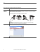
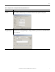
Add a Kinetix 350 Drive to an RSLogix 5000 Project Chapter 2 5. Select the Kinetix 350 drive and click Create. The Select Module Type dialog box may appear differently depending on which Logix5000 controller your application uses and, thus, what version of RSLogix 5000 software is used. The New Module dialog box opens. 6. Configure the new drive. a. Type the drive Name. b. Click an Ethernet Address option. In this example, the Private Network address is selected. c.
Chapter 2 Add a Kinetix 350 Drive to an RSLogix 5000 Project 8. From the Electronic Keying pull-down menu, choose Disable Keying. IMPORTANT The Disable Keying selection ensures that you will easily complete the taks. In typical applications, we recommend you avoid using Disable Keying whenever possible. 9. Click OK twice to close the Module Definition dialog box and the Module Properties dialog box successively. 10. Right-click the 2097-V31PR2-LM drive and choose Properties.
Add a Kinetix 350 Drive to an RSLogix 5000 Project Chapter 2 13. Type the axis Name. AXIS_CIP_DRIVE is the default Data Type. 14. Change the Scope to your controller project. In this case, the Scope is Kinetix_350_project. 15. Click Create and Close. 16. When the Module Properties dialog box appears, the new axis appears in the Axis 1: field. 17. Click OK. Configure the Motion Group Complete these steps to configure the motion group. 1.
Chapter 2 Add a Kinetix 350 Drive to an RSLogix 5000 Project 2. Type the new motion group Name. 3. Click Create and Close. The new motion group appears under the Motion Groups folder. 4. Right-click the new motion group and choose Properties. The Motion Group Properties dialog box opens. 5. Click the Axis Assignment tab and move the axis you created beginning at step 12 from Unassigned to Assigned. 6. Click OK.
Add a Kinetix 350 Drive to an RSLogix 5000 Project Chapter 2 Configure Axis Properties Complete these steps to configure the properties for Axis_1. 1. Right-click Axis_1 in the Controller Organizer and choose Properties. The Axis Properties dialog box opens. 2. Click the Motor category. The Motor Device Specification dialog box opens. 3. From the Data Source pull-down menu, choose Catalog Number. 4. Click Change Catalog. The Change Catalog Number dialog box opens. 5. Select the motor catalog number.
Chapter 2 Add a Kinetix 350 Drive to an RSLogix 5000 Project 6. Click OK to close the Change Catalog Number dialog box. Motor data specific to your motor appears in the Motor category. 7. Click Apply. Motor data specific to your MPL-A310P-MJ72AA motor appears in the Motion category. You do not need to change the parameters in the other categories to complete the tasks described in this quick start. 8. Click OK to close the Axis Properties dialog box. 9. Save the file and download it to the controllers.
Add a Kinetix 350 Drive to an RSLogix 5000 Project Chapter 2 Apply Power to the Kinetix 350 Drive System Before beginning this section, verify that you have wired and configured your Kinetix 350 drive and your controller’s EtherNet/IP network port correctly. SHOCK HAZARD: To avoid hazard of electrical shock, perform all mounting and wiring of the Bulletin 2097 drive prior to applying power. Once power is applied, connector terminals may have voltage present even when not in use.
Chapter 2 Add a Kinetix 350 Drive to an RSLogix 5000 Project 5. Observe the status indicators on the 2097-V31PR2-LM drive. The indicators include the following: • N - Network • M- Module • A - Axis The network and module status indicators should be in the steady green state and the axis status indicator should be in the flashing green state. If the status indicators are not in these states you must determine what condition is preventing it.
Add a Kinetix 350 Drive to an RSLogix 5000 Project Chapter 2 Table 2 - Drive Status Indicators Status Indicator Condition Status Axis Off One of the following conditions exists: • Off • Initialization is in process - Bus not operating • Shutdown is in process - Bus not operating • Pre-charge is in process - Bus not operating Flashing red/green Self-test (power-up diagnostics) in process Flashing green One of the following conditions exists: • Initialization is in process- Bus is operating • Axis
Chapter 2 Add a Kinetix 350 Drive to an RSLogix 5000 Project Test the Axis IMPORTANT This section assumes that your 2097-V31PR2-LM drive’s status indicators show that drive is operating as expected. If the status indicators do not reflect a fully operational drive state, as described in Table 2 on page 42, use the table to address any issues with regard to the drive’s stater before proceeding with this section. Complete these steps to test the axes. 1. Remove the load from Axis_1. 2.
Add a Kinetix 350 Drive to an RSLogix 5000 Project Chapter 2 The RSLogix 5000 - Motor and Feedback Test dialog box opens. The Test State is Executing. IMPORTANT During this time, the shaft on your motor should be turning. Additionally, the axis status indicator should be in a steady green state. When the test completes successfully, the Test State changes from Executing to Passed. 8. Click OK. A dialog box opens to confirm that the shaft’s direction was correct. 9. Click Yes. 10.
Chapter 2 Add a Kinetix 350 Drive to an RSLogix 5000 Project Tune an Axis For the purposes of this quick start, you do not need to tune the axis. Some applications, however, require the use of tuning to improve the application’s use of Integrated Motion on an EtherNet/IP network. Tuning conditions and parameters are defined by each individual application.
Index A axis properties configure 39-40 C configure axis properties 39-40 motion group 37-38 connections apply motor cable shield clamp 25 apply power to drive 41 drive to EtherNet/IP network 27 hardware 10, 18-27 wire input power connector 23 wire motor feedback connector 26 wire motor power connector 24 wire safe torque-off connector 18 D drive preparation mount 16-17 E EtherNet/IP network connect drive 27 H hardware example control system 10 ground drive 17 input power connector 23 motor cable shield
Index Notes: 48 Rockwell Automation Publication IASIMP-QS032A-EN-P - March 2012
Rockwell Automation Support Rockwell Automation provides technical information on the Web to assist you in using its products. At http://www.rockwellautomation.com/support/, you can find technical manuals, a knowledge base of FAQs, technical and application notes, sample code and links to software service packs, and a MySupport feature that you can customize to make the best use of these tools.