
User guide

10 Instruction Manual D2-3536
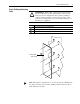
Step 8: Verifying the
Installation
Task Description
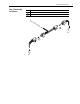
Disconnect connector (J3 on PMA board for LiquiFlo 1.0 drives or J4 on PMC board for
LiquiFlo 1.5 drives)
Confirm continuity between the points specified in either Table A
or Ta bl e B
Reconnect connector (J3 on PMA board for LiquiFlo 1.0 drives or J4 on PMC board for
LiquiFlo 1.5 drives)
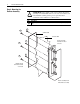
A
B
C
J3
Pin 1
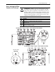
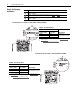
Continuity Checks on LiquiFlo 1.0 Drives (M/N’s 50LXXX, 64LXXXX)
Table A J3 Continuity Tests
Test Points
(1)
(1)
If you are unfamiliar with continuity tests, refer to Performing Continuity
Test s on page 11.
Meter ReadingJ3 End of Cable
Resistor Assembly
End of Cable
(2)
(2)
See Wiring Diagram for Reference on page 13.
J3:Pin 1 BUS (+) Continuity or
approximately zero ohms
J3:Pin 3 BUS MID
J3:Pin 5 BUS (-)
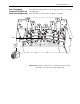
A
B
C
Pin 1
J4
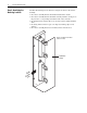
Continuity Checks on LiquiFlo 1.5 Drives (M/N’s LF150XXXX)
Table B J4 Continuity Tests
Test Points
(1)
(1)
If you are unfamiliar with continuity tests, refer to Performing Continuity
Te sts on page 11.
Meter ReadingJ4 End of Cable
Resistor Assembly
End of Cable
(2)
(2)
See Wiring Diagram for Reference on page 13.
J4:Pin 1 BUS (+) Continuity or
approximately zero ohms
J4:Pin 3 BUS MID
J4:Pin 5 BUS (-)
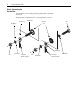
A
B
C