
Manual

2 Instruction Manual D2-3535
What You Need to Do
To install the external bus resistor kit you need to:
❐ Step 1: Verify that the DC Bus Capacitors are discharged
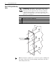
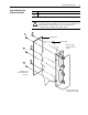
❐ Step 2: Identify a mounting location for the resistor assembly
❐ Step 3: Drill mounting holes for the resistor assembly, using the
template
❐ Step 4: Mount the resistor assembly
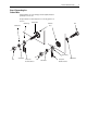
❐ Step 5: Unplug connectors P1 and P2, and route harness
❐ Step 6: Connect the ground wire
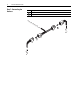
❐ Step 7: Connect the harness
❐ Step 8: Verify installation
❐ Step 9: Register installation
Step 1: Verifying the DC Bus
Capacitors are Discharged
!
ATTENTION: DC Bus capacitors retain hazardous voltages
after input power has been disconnected. After disconnecting
input power, wait five (5) minutes for the DC bus capacitors to
discharge and then check the voltage with a voltmeter to ensure
that the DC bus capacitors are discharged before touching any
internal components. Failure to observe this precaution could
result in severe bodily injury or loss of life.
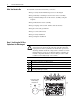
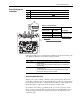
Task Description
Turn off and lock out input power. Wait five minutes
Verify that there is no voltage at the drive’s input power terminals
Remove front cover
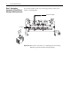
Measure the DC bus potential with a voltmeter while standing on a non-conductive surface
and wearing insulated gloves (1000V)
A
B
C
D
Made in USA
BARCODE
U31
FUSE1
C50
D66
D65
D64
C49
C44
U35
C43
C42
C45
U36
C39
D60
C41
D56
T11
Q6
D49
D50
R37
C35
U21
D52
D51
C36
C31
C32
FUSE2
U29
C40
R42
R40
U30
R38
L2
C37
C38
ASSY
D48
C47
TP4TP5TP6 TP3
C46
U37
J8
D63
D61
R43
R41
U32
U33
R39 D57
D58
C34
U22
U23
U16
U17
D59
D62
DS2
U34
C48
DS3
DS4
U24
U27
D54
U18
U26
D45
D53
D47
U19
C30
D46
U28
D55
U25
U20
R15
C27
Q5
R35
T10
U14
DS1
R36
D29
D24
U6
C22
D26
C23
T3
L1
C20
C33
U15
D43
D44
T9
R29 R30
D38
D36
U13
C24
D33
D27
D28
T4 T5
R31
D10
D16
Q4
T1
R19
D12
T2
D11
U1 C13
C7
C5
C4
C1
Q2Q1
C2 C3
R23
C14
D17 R22
D18
C15
C8
D19
C16 R24
C9
RV5
RV3
D6
D1
RV4
J6
J1
R1
RV1
R2
R3
J2
R4
R14
J3
D42
C29
C25
D35
D34
D31
U8
D30
D32
U9
R28
D20
TP1 TP2
U3
R32
U10
D39
C28
D40
D41
D37
C26
U11
R33
U7
D25
T6
C21
U4
U5
T7 T8
U2
Q3
R20
R21
D13
D14
D2
D3
D7
D8 D9
D4
D5
D15
D21
C10
D22
R25C17
C18 R26
C11
C12
C6
RV6
RV7
R34
U12
C19
D23
R27
J7
RV8
RV2
R16 R17
R8 R9 R10
R18
J4
R5
R11 R12 R13 R6
J5
R7
1
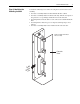
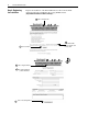
TP2TP1
D
Test Points for initial
DC Bus Voltage
Measurement
Pos
(+)
Neg
(-)