
Owner's manual
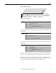
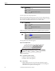
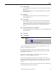
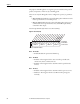

Table Of Contents
- Front Cover
- Important User Information
- Summary of Changes
- Table of Contents
- Introduction
- About the Drive
- Identifying the Drive by Cabinet Assembly ID Number
- LiquiFlo 2.0 Drive Component Locations
- Identifying the Power Module by Model Number
- AC Line I/O Board Description (Frame 3 Only)
- Standard I/O Board Description (Frame 3 Only)
- Combined I/O Board Description (Frame 4 Only)
- DPI Communication Ports
- Optional Equipment
- Planning the Installation
- Mounting The Power Module and Grounding the Drive
- Installing Input and Output Power Wiring
- Completing the Installation
- Using the Start-up Routines
- Programming Basics
- Parameter Descriptions
- Troubleshooting the Drive
- Verify that the DC Bus Capacitors are Discharged Before Servicing the Drive
- Determining Drive Status Using the Status LEDs
- About Alarms
- About Faults
- Diagnostic Parameters
- Common Symptoms and Corrective Actions
- Replacement Parts
- Board Replacement, Firmware Setup Procedures
- Troubleshooting the Drive Using the OIM
- Checking the Power Modules with Input Power Off
- Technical Specifications
- Using the OIM
- Installing and Removing the OIM
- Display Description
- OIM Menu Structure
- Powering Up and Adjusting the OIM
- Selecting a Device in the System
- Using the OIM to Program the Drive
- Monitoring the Drive Using the Process Display Screen on the OIM
- Displaying and Changing the OIM Reference
- Customizing the Process Display Screen
- Customizing the Function Keys
- Controlling the Drive From the OIM
- LiquiFlo 2.0 Drive Frame 3 Wiring Diagrams
- LiquiFlo 2.0 Drive Frame 4 Wiring Diagrams
- Index
- Back Cover

Rockwell Automation Publication D2-3518-3 - May 2013 97
Chapter 9
Bit 2 – Preload Mode
• Enabled = Initializes the PI integrator to the commanded speed while the
PI is disabled.
• Disabled = The PI integrator is loaded with the PI Pre-load (133) while
the PI is disabled.
Bit 3 – Ramp Ref
• Enables/disables ramping the reference used from PI Feedback to the
selected PI Reference.
Bit 4 – Zero Clamp
• Enables/disables option to limit operation so that the output frequency
always has the same sign as the master speed reference. This limits the
possible drive action to one direction only. Output from the drive is from
zero to maximum frequency forward or zero to maximum frequency
reverse.
Bit 5 – Feedback Sqrt (Square Root Feedback)
• Enables/disables the option of using the square root of the feedback signal
as the PI feedback.
Bit 6 – Stop Mode
Bit 7 – Anti-Windup
Controls the PI regulator. Note that you must use a datalink to write to this
parameter interactively from a network.
PI control allows the drive to take a reference signal (setpoint) and an actual
signal (feedback) and automatically adjust the speed of the drive to match the
actual signal to the reference.
Proportional control (P) adjusts the output based on the size of the error
(larger error = proportionally larger correction).
Integral control (I) adjusts the output based on the duration of the error. The
integral control by itself is a ramp output correction. This type of control gives a
smoothing effect to the output and continues to integrate until zero error is
achieved.
By itself, integral control is slower than many applications require, and therefore,
is combined with proportional control (PI).
125 PI Control
Range: See Figure 41
Default: See Figure 41
Access: 1 Path: Speed Command > Process PI
See also: 124...138