
Owner's manual
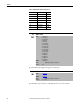
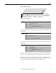

Table Of Contents
- Front Cover
- Important User Information
- Summary of Changes
- Table of Contents
- Introduction
- About the Drive
- Identifying the Drive by Cabinet Assembly ID Number
- LiquiFlo 2.0 Drive Component Locations
- Identifying the Power Module by Model Number
- AC Line I/O Board Description (Frame 3 Only)
- Standard I/O Board Description (Frame 3 Only)
- Combined I/O Board Description (Frame 4 Only)
- DPI Communication Ports
- Optional Equipment
- Planning the Installation
- Mounting The Power Module and Grounding the Drive
- Installing Input and Output Power Wiring
- Completing the Installation
- Using the Start-up Routines
- Programming Basics
- Parameter Descriptions
- Troubleshooting the Drive
- Verify that the DC Bus Capacitors are Discharged Before Servicing the Drive
- Determining Drive Status Using the Status LEDs
- About Alarms
- About Faults
- Diagnostic Parameters
- Common Symptoms and Corrective Actions
- Replacement Parts
- Board Replacement, Firmware Setup Procedures
- Troubleshooting the Drive Using the OIM
- Checking the Power Modules with Input Power Off
- Technical Specifications
- Using the OIM
- Installing and Removing the OIM
- Display Description
- OIM Menu Structure
- Powering Up and Adjusting the OIM
- Selecting a Device in the System
- Using the OIM to Program the Drive
- Monitoring the Drive Using the Process Display Screen on the OIM
- Displaying and Changing the OIM Reference
- Customizing the Process Display Screen
- Customizing the Function Keys
- Controlling the Drive From the OIM
- LiquiFlo 2.0 Drive Frame 3 Wiring Diagrams
- LiquiFlo 2.0 Drive Frame 4 Wiring Diagrams
- Index
- Back Cover
96 Rockwell Automation Publication D2-3518-3 - May 2013
Chapter 9
Sets the response time of slip compensation.
Parameters in the Slip Comp Group (121...123) are used to enable and tune the
slip compensation regulator. To allow the slip compensation regulator to control
drive operation, Speed Mode (80) must be set to 1 (Slip Comp).
Displays the present amount of adjustment being applied as slip compensation.
Selects specific features of the PI regulator.
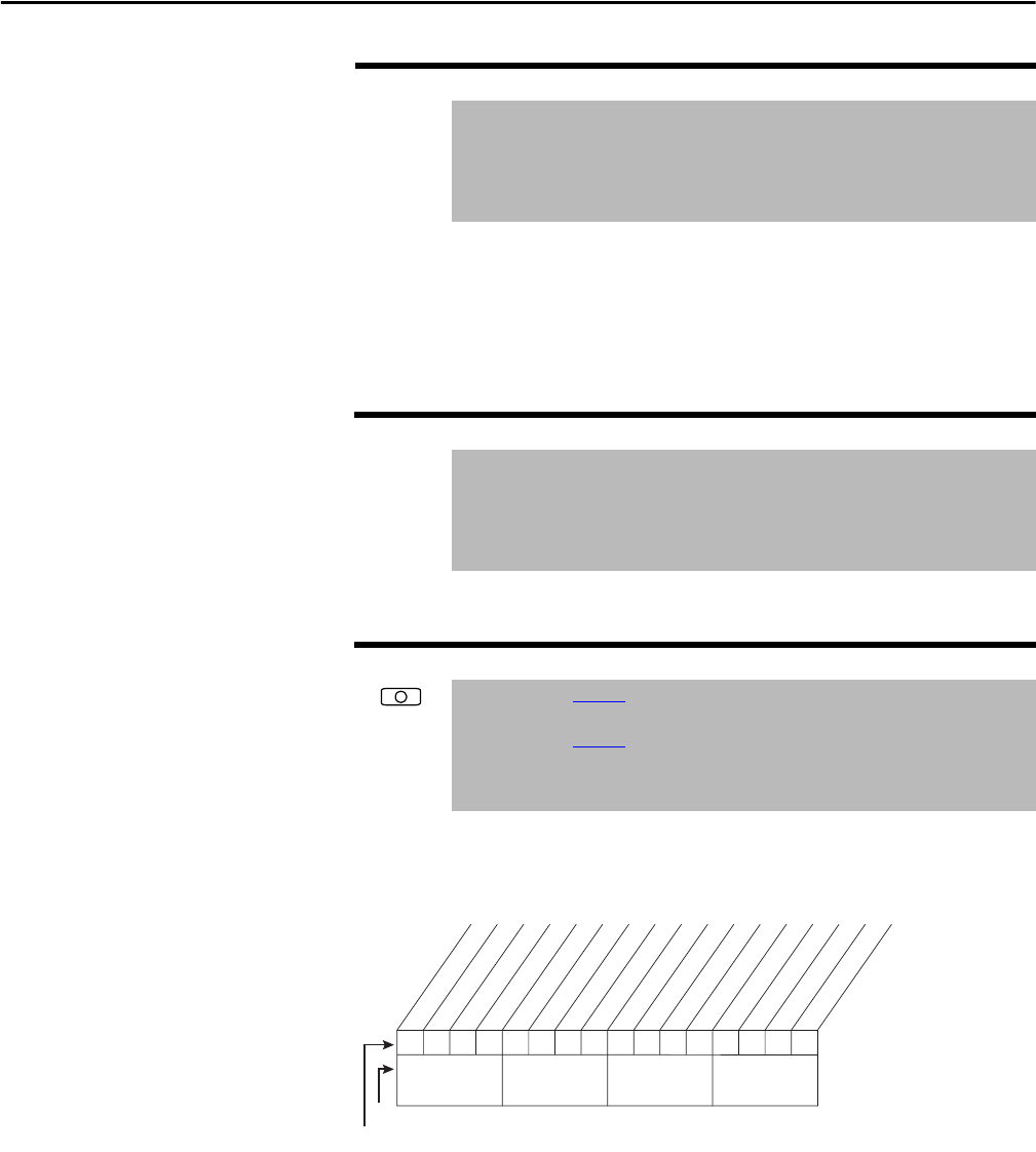
Figure 40 - PI Configuration (124)
Bit 0 – Excl Mode (Exclusive Mode)
• Enabled = Selects speed regulation.
• Disabled = Selects trim regulation.
Bit 1 – Invert Error
• Enables/disables the option to invert the sign of the PI error signal.
Enabling this feature creates a decrease in output for an increasing error
and an increase in output for a decreasing error.
122 Slip Comp Gain
Range: 1.0...100.0 [0.1]
Default: 40.0
Access: 1 Path: Speed Command > Slip Comp
See also: 80, 121, 122
123 Slip RPM Meter
Range: -/+300.0 RPM
Default: Read Only
Access: 1 Path: Speed Command > Slip Comp
See also: 80, 121, 122
124 PI Configuration
Range: See Figure 40
Default: See Figure 40
Access: 1 Path: Speed Command > Process PI
See also: 125...138
00000000xxxxxxxx
0011234567891112131415
1=Enabled
0=Disabled
x =Reserved
Bit #
Factory Default Bit Values
Excl Mode
Invert Error
Preload Mode
Ramp Ref
Zero Clamp
Feedbak Sqrt
Stop Mode
Anti-Windup
Nibble 1Nibble 2Nibble 3Nibble 4