
Owner's manual
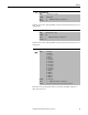
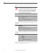
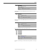
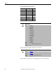
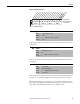
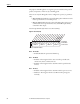

Table Of Contents
- Front Cover
- Important User Information
- Summary of Changes
- Table of Contents
- Introduction
- About the Drive
- Identifying the Drive by Cabinet Assembly ID Number
- LiquiFlo 2.0 Drive Component Locations
- Identifying the Power Module by Model Number
- AC Line I/O Board Description (Frame 3 Only)
- Standard I/O Board Description (Frame 3 Only)
- Combined I/O Board Description (Frame 4 Only)
- DPI Communication Ports
- Optional Equipment
- Planning the Installation
- Mounting The Power Module and Grounding the Drive
- Installing Input and Output Power Wiring
- Completing the Installation
- Using the Start-up Routines
- Programming Basics
- Parameter Descriptions
- Troubleshooting the Drive
- Verify that the DC Bus Capacitors are Discharged Before Servicing the Drive
- Determining Drive Status Using the Status LEDs
- About Alarms
- About Faults
- Diagnostic Parameters
- Common Symptoms and Corrective Actions
- Replacement Parts
- Board Replacement, Firmware Setup Procedures
- Troubleshooting the Drive Using the OIM
- Checking the Power Modules with Input Power Off
- Technical Specifications
- Using the OIM
- Installing and Removing the OIM
- Display Description
- OIM Menu Structure
- Powering Up and Adjusting the OIM
- Selecting a Device in the System
- Using the OIM to Program the Drive
- Monitoring the Drive Using the Process Display Screen on the OIM
- Displaying and Changing the OIM Reference
- Customizing the Process Display Screen
- Customizing the Function Keys
- Controlling the Drive From the OIM
- LiquiFlo 2.0 Drive Frame 3 Wiring Diagrams
- LiquiFlo 2.0 Drive Frame 4 Wiring Diagrams
- Index
- Back Cover
Rockwell Automation Publication D2-3518-3 - May 2013 95
Chapter 9
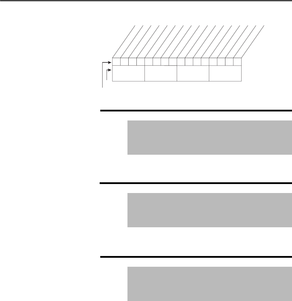
Figure 39 - Trim Out Select (118)
Scales the upper value of the Trim In Select (117) selection when the source is an
analog input.
Scales the lower value of the Trim In Select (117) selection when the source is an
analog input.
Sets the amount of compensation to drive output at motor FLA. If parameter 61
(Autotune) = 3 (Calculate), changes made to this parameter are not accepted.
Parameters in the Slip Comp Group (121...123) are used to enable and tune the
slip compensation regulator. To allow the slip compensation regulator to control
drive operation, Speed Mode (80) must be set to 1 (Slip Comp).
119 Trim Hi
Range: -/+Maximum Speed [0.1 Hz]
Default: 60.0 Hz
Access: 1 Path: Speed Command > Speed Trim
See also: 82, 117
120 Trim Lo
Range: -/+Maximum Speed [0.1 Hz]
Default: 0.0 Hz
Access: 1 Path: Speed Command > Speed Trim
See also: 117
121 Slip RPM @ FLA
Range: 0.0...1200.0 RPM
Default: Based on Motor NP RPM
Access: 1 Path: Speed Command > Slip Comp
See also: 61, 80, 122, 123
0xx 0xxxxxxxxxxxx
0011234567891112131415
1=Trimmed
0=Not Trimmed
x=Reserved
Bit #
Factory Default Bit Values
Trim Ref A
Trim Ref B
Nibble 1Nibble 2Nibble 3Nibble 4