
Owner's manual


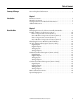
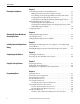
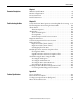
Table Of Contents
- Front Cover
- Important User Information
- Summary of Changes
- Table of Contents
- Introduction
- About the Drive
- Identifying the Drive by Cabinet Assembly ID Number
- LiquiFlo 2.0 Drive Component Locations
- Identifying the Power Module by Model Number
- AC Line I/O Board Description (Frame 3 Only)
- Standard I/O Board Description (Frame 3 Only)
- Combined I/O Board Description (Frame 4 Only)
- DPI Communication Ports
- Optional Equipment
- Planning the Installation
- Mounting The Power Module and Grounding the Drive
- Installing Input and Output Power Wiring
- Completing the Installation
- Using the Start-up Routines
- Programming Basics
- Parameter Descriptions
- Troubleshooting the Drive
- Verify that the DC Bus Capacitors are Discharged Before Servicing the Drive
- Determining Drive Status Using the Status LEDs
- About Alarms
- About Faults
- Diagnostic Parameters
- Common Symptoms and Corrective Actions
- Replacement Parts
- Board Replacement, Firmware Setup Procedures
- Troubleshooting the Drive Using the OIM
- Checking the Power Modules with Input Power Off
- Technical Specifications
- Using the OIM
- Installing and Removing the OIM
- Display Description
- OIM Menu Structure
- Powering Up and Adjusting the OIM
- Selecting a Device in the System
- Using the OIM to Program the Drive
- Monitoring the Drive Using the Process Display Screen on the OIM
- Displaying and Changing the OIM Reference
- Customizing the Process Display Screen
- Customizing the Function Keys
- Controlling the Drive From the OIM
- LiquiFlo 2.0 Drive Frame 3 Wiring Diagrams
- LiquiFlo 2.0 Drive Frame 4 Wiring Diagrams
- Index
- Back Cover

Rockwell Automation Publication D2-3518-3 - May 2013 9
Chapter 1
Introduction
This manual is intended for qualified electrical and plumbing personnel familiar
with installing, programming, and maintaining AC drives.
This manual contains information on:
• Installing and wiring the LiquiFlo 2.0 AC drive
• Programming the drive
• Troubleshooting the drive
ATTENTION: Only qualified electrical personnel familiar with the construction
and operation of this equipment and the hazards involved should install, adjust,
operate, or service this equipment. Read and understand this manual and other
applicable manuals in their entirety before proceeding. Failure to observe this
precaution could result in severe bodily injury or loss of life.
ATTENTION: DC bus capacitors retain hazardous voltages after input power has
been disconnected. After disconnecting input power, wait 5 minutes for the DC
bus capacitors to discharge and then check the voltage with a voltmeter to
ensure the DC bus capacitors are discharged before touching any internal
components. Failure to observe this precaution could result in severe bodily
injury or loss of life.
ATTENTION: The drive can operate at and maintain zero speed. You are
responsible for assuring safe conditions for operating personnel by providing
suitable guards, audible or visual alarms, or other devices to indicate that the
drive is operating or may operate at or near zero speed. Failure to observe this
precaution could result in severe bodily injury or loss of life.
ATTENTION: Do not install modification kits with power applied to the drive.
Disconnect and lock out incoming power before attempting such installation or
removal. Failure to observe this precaution could result in severe bodily injury or
loss of life.
ATTENTION: You must provide an external, hardwired emergency stop circuit
outside of the drive circuitry. This circuit must disable the system in case of
improper operation. Uncontrolled machine operation may result if this
procedure is not followed. Failure to observe this precaution could result in
bodily injury.