
Owner's manual
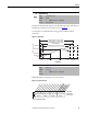
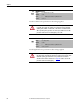
Table Of Contents
- Front Cover
- Important User Information
- Summary of Changes
- Table of Contents
- Introduction
- About the Drive
- Identifying the Drive by Cabinet Assembly ID Number
- LiquiFlo 2.0 Drive Component Locations
- Identifying the Power Module by Model Number
- AC Line I/O Board Description (Frame 3 Only)
- Standard I/O Board Description (Frame 3 Only)
- Combined I/O Board Description (Frame 4 Only)
- DPI Communication Ports
- Optional Equipment
- Planning the Installation
- Mounting The Power Module and Grounding the Drive
- Installing Input and Output Power Wiring
- Completing the Installation
- Using the Start-up Routines
- Programming Basics
- Parameter Descriptions
- Troubleshooting the Drive
- Verify that the DC Bus Capacitors are Discharged Before Servicing the Drive
- Determining Drive Status Using the Status LEDs
- About Alarms
- About Faults
- Diagnostic Parameters
- Common Symptoms and Corrective Actions
- Replacement Parts
- Board Replacement, Firmware Setup Procedures
- Troubleshooting the Drive Using the OIM
- Checking the Power Modules with Input Power Off
- Technical Specifications
- Using the OIM
- Installing and Removing the OIM
- Display Description
- OIM Menu Structure
- Powering Up and Adjusting the OIM
- Selecting a Device in the System
- Using the OIM to Program the Drive
- Monitoring the Drive Using the Process Display Screen on the OIM
- Displaying and Changing the OIM Reference
- Customizing the Process Display Screen
- Customizing the Function Keys
- Controlling the Drive From the OIM
- LiquiFlo 2.0 Drive Frame 3 Wiring Diagrams
- LiquiFlo 2.0 Drive Frame 4 Wiring Diagrams
- Index
- Back Cover
Rockwell Automation Publication D2-3518-3 - May 2013 89
Chapter 9
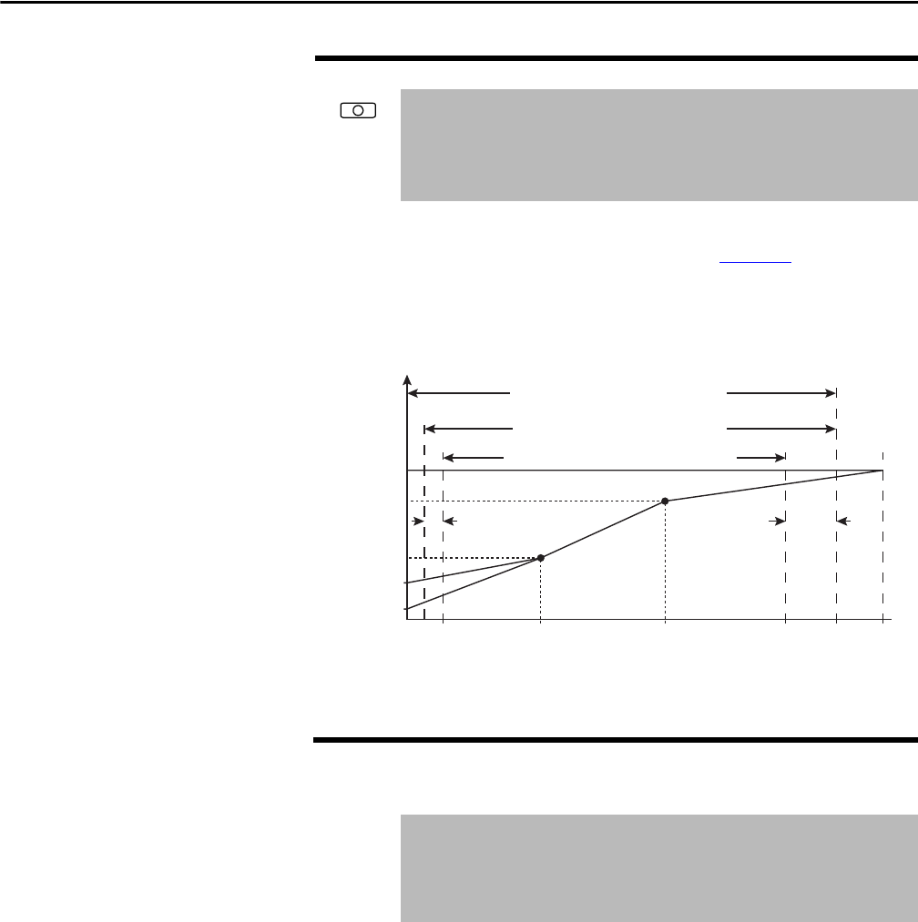
Sets the incremental amount of the output frequency (above Maximum Speed)
allowable for functions such as slip compensation. See Figure 38
.
Maximum Speed + Overspeed Limit must be ≤ to Maximum Frequency.
Figure 38 - Speed Limits
Sets a frequency at which the drive will not operate (also called an avoidance
frequency). Requires that both Skip Frequency 1...3 and Skip Frequency Band
(87) be set to a value other than 0.
83 Overspeed Limit
Range: 0.0...20.0 Hz [0.1 Hz]
Default: 10.0 Hz
Access: 1 Path: Speed Command > Spd Mode & Limits
See also: 55, 82
84
85
86
Skip Frequency 1
Skip Frequency 2
Skip Frequency 3
Range: -/+250.0 [0.1 Hz]
Default: 0.0 Hz
Access: 1 Path: Speed Command > Spd Mode & Limits
See also: 87
Allowable Output Frequency Range
Bus Regulation or Current Limit
V
o
l
t
a
g
e
Frequency
Allowable Output Frequency Range
Normal Operation
Allowable Reference Frequency Range
Frequency Trim due to
Speed Control Mode
Max Volts
Motor Volts
Break Volts
Start Boost
Run
0 Min
Speed
Motor
Hz
Max
Speed
Output
Freq Limit
Max
Freq
Break
Frequency
Overspeed
Limit