
Owner's manual
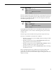
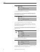
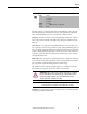
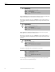
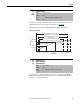
Table Of Contents
- Front Cover
- Important User Information
- Summary of Changes
- Table of Contents
- Introduction
- About the Drive
- Identifying the Drive by Cabinet Assembly ID Number
- LiquiFlo 2.0 Drive Component Locations
- Identifying the Power Module by Model Number
- AC Line I/O Board Description (Frame 3 Only)
- Standard I/O Board Description (Frame 3 Only)
- Combined I/O Board Description (Frame 4 Only)
- DPI Communication Ports
- Optional Equipment
- Planning the Installation
- Mounting The Power Module and Grounding the Drive
- Installing Input and Output Power Wiring
- Completing the Installation
- Using the Start-up Routines
- Programming Basics
- Parameter Descriptions
- Troubleshooting the Drive
- Verify that the DC Bus Capacitors are Discharged Before Servicing the Drive
- Determining Drive Status Using the Status LEDs
- About Alarms
- About Faults
- Diagnostic Parameters
- Common Symptoms and Corrective Actions
- Replacement Parts
- Board Replacement, Firmware Setup Procedures
- Troubleshooting the Drive Using the OIM
- Checking the Power Modules with Input Power Off
- Technical Specifications
- Using the OIM
- Installing and Removing the OIM
- Display Description
- OIM Menu Structure
- Powering Up and Adjusting the OIM
- Selecting a Device in the System
- Using the OIM to Program the Drive
- Monitoring the Drive Using the Process Display Screen on the OIM
- Displaying and Changing the OIM Reference
- Customizing the Process Display Screen
- Customizing the Function Keys
- Controlling the Drive From the OIM
- LiquiFlo 2.0 Drive Frame 3 Wiring Diagrams
- LiquiFlo 2.0 Drive Frame 4 Wiring Diagrams
- Index
- Back Cover
88 Rockwell Automation Publication D2-3518-3 - May 2013
Chapter 9
Sets the low limit for the speed reference after scaling is applied.
Sets the high limit for the speed reference after scaling is applied.
81 Minimum Speed
Range: 0.0 to Maximum Speed [0.1 Hz]
Default: 0.0 Hz
Access: 0 Path: Speed Command > Spd Mode & Limits
See also: 83, 92, 95
ATTENTION: The drive can operate at and maintain zero speed. You are
responsible for assuring safe conditions for operating personnel by providing
suitable guards, audible or visual alarms, or other devices to indicate that the
drive is operating or may operate at or near zero speed. Failure to observe this
precaution could result in severe bodily injury or loss of life.
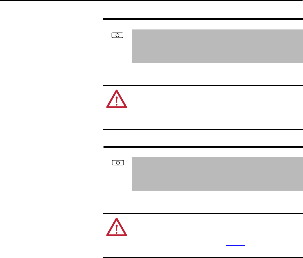
82 Maximum Speed
Range: 5.0...250.0 [0.1 Hz]
Default: 60.0 Hz
Access: 0 Path: Speed Command > Spd Mode & Limits
See also: 55, 83, 91, 94, 202
ATTENTION: You are responsible for ensuring that driven machinery, all drive-
train mechanisms, and application material are capable of safe operation at the
maximum operating speed of the drive. Overspeed detection in the drive
determines when the drive shuts down. See Figure 38
. Failure to observe this
precaution could result in bodily injury.