
Owner's manual
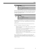
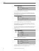
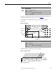
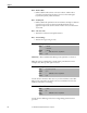
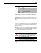
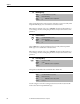
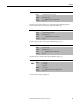
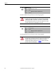
Table Of Contents
- Front Cover
- Important User Information
- Summary of Changes
- Table of Contents
- Introduction
- About the Drive
- Identifying the Drive by Cabinet Assembly ID Number
- LiquiFlo 2.0 Drive Component Locations
- Identifying the Power Module by Model Number
- AC Line I/O Board Description (Frame 3 Only)
- Standard I/O Board Description (Frame 3 Only)
- Combined I/O Board Description (Frame 4 Only)
- DPI Communication Ports
- Optional Equipment
- Planning the Installation
- Mounting The Power Module and Grounding the Drive
- Installing Input and Output Power Wiring
- Completing the Installation
- Using the Start-up Routines
- Programming Basics
- Parameter Descriptions
- Troubleshooting the Drive
- Verify that the DC Bus Capacitors are Discharged Before Servicing the Drive
- Determining Drive Status Using the Status LEDs
- About Alarms
- About Faults
- Diagnostic Parameters
- Common Symptoms and Corrective Actions
- Replacement Parts
- Board Replacement, Firmware Setup Procedures
- Troubleshooting the Drive Using the OIM
- Checking the Power Modules with Input Power Off
- Technical Specifications
- Using the OIM
- Installing and Removing the OIM
- Display Description
- OIM Menu Structure
- Powering Up and Adjusting the OIM
- Selecting a Device in the System
- Using the OIM to Program the Drive
- Monitoring the Drive Using the Process Display Screen on the OIM
- Displaying and Changing the OIM Reference
- Customizing the Process Display Screen
- Customizing the Function Keys
- Controlling the Drive From the OIM
- LiquiFlo 2.0 Drive Frame 3 Wiring Diagrams
- LiquiFlo 2.0 Drive Frame 4 Wiring Diagrams
- Index
- Back Cover
82 Rockwell Automation Publication D2-3518-3 - May 2013
Chapter 9
Sets the fault threshold for motor current imbalance.
If inverter Imbalance Count (221) exceeds inverter Imbalance Limit (49) for
longer than the time in inverter Imbalance Time (50), the drive faults with the
Motor I Imbalance fault (fault 37).
Sets the time delay in generating a motor current imbalance fault.
If inverter Imbalance Count (221) exceeds inverter Imbalance Limit (49) for
longer than the time in inverter Imbalance Time (50), the drive faults with the
Motor I Imbalance fault (fault 37).
Also sets the time delay in generating a Current Feedback Lost Fault (fault 35). If
this parameter is set to exactly 10.0 seconds, then the Current Feedback Lost
Fault does not occur.
Sets the method of motor torque production.
Sets the highest RMS voltage the drive will output. See description of rectifier
Max Motor Volts parameter (107 in rectifiers parameters).
49 Imbalance Limit
Range: 0.0...40.0 [0.1%]
Default: 10.0
Access: 1 Path: Motor Control > Motor Data
See also: 50, 221
50 Imbalance Time
Range: 1.0...10.0 [0.1 sec]
Default: 5.0
Access: 1 Path: Motor Control > Motor Data
See also: 49, 221
53 Torque Perf Mode
Range: 0 = Sensrls Vect
1 = SV Economize
2 = Custom V/Hz
3 = Fan/Pmp-V/Hz
Default: 0 = Sensrls Vect
Access: 0 Path: Motor Control > Torq Attributes
See also: 62, 63, 69, 70
54 Maximum Voltage
Range: (Rated Volts x 0.25) to Rated Volts [0.1V AC]
Default: Drive Rated Volts
Access: 0 Path: Motor Control > Torq Attributes
See also: rectifier 107