
Owner's manual
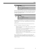
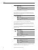
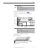
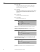
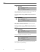
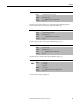
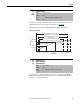
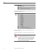
Table Of Contents
- Front Cover
- Important User Information
- Summary of Changes
- Table of Contents
- Introduction
- About the Drive
- Identifying the Drive by Cabinet Assembly ID Number
- LiquiFlo 2.0 Drive Component Locations
- Identifying the Power Module by Model Number
- AC Line I/O Board Description (Frame 3 Only)
- Standard I/O Board Description (Frame 3 Only)
- Combined I/O Board Description (Frame 4 Only)
- DPI Communication Ports
- Optional Equipment
- Planning the Installation
- Mounting The Power Module and Grounding the Drive
- Installing Input and Output Power Wiring
- Completing the Installation
- Using the Start-up Routines
- Programming Basics
- Parameter Descriptions
- Troubleshooting the Drive
- Verify that the DC Bus Capacitors are Discharged Before Servicing the Drive
- Determining Drive Status Using the Status LEDs
- About Alarms
- About Faults
- Diagnostic Parameters
- Common Symptoms and Corrective Actions
- Replacement Parts
- Board Replacement, Firmware Setup Procedures
- Troubleshooting the Drive Using the OIM
- Checking the Power Modules with Input Power Off
- Technical Specifications
- Using the OIM
- Installing and Removing the OIM
- Display Description
- OIM Menu Structure
- Powering Up and Adjusting the OIM
- Selecting a Device in the System
- Using the OIM to Program the Drive
- Monitoring the Drive Using the Process Display Screen on the OIM
- Displaying and Changing the OIM Reference
- Customizing the Process Display Screen
- Customizing the Function Keys
- Controlling the Drive From the OIM
- LiquiFlo 2.0 Drive Frame 3 Wiring Diagrams
- LiquiFlo 2.0 Drive Frame 4 Wiring Diagrams
- Index
- Back Cover
Rockwell Automation Publication D2-3518-3 - May 2013 81
Chapter 9
Selects the output frequency below which the motor operating current is derated.
The motor thermal overload then generates a fault at lower levels of current. For
all settings of overload Hz other than zero, the overload capacity is reduced to
70% when output frequency is zero.
Sets the RMS amps threshold for motor overload fault. In order for the motor
overload fault (48) to occur, it must be enabled using inverter parameter Fault
Config 1 (238).
The drive output current is visible in inverter parameter Output Current (3).
The motor overload fault occurs under these conditions:
• If the drive output (motor) current is 138% of Motor OL Amps, the fault
occurs at 1.5 seconds.
• If the drive output (motor) current is greater than 138% of Motor OL
Amps, the fault occurs in less than 1.5 seconds.
• If the drive output (motor) current is between 102% and 138% of Motor
OL Amps, the fault occurs in greater than 1.5 seconds.
• If the drive output (motor) current is less than 102% of Motor OL Amps,
the fault does not occur.
Motor overload fault percent trip is visible in inverter parameter Motor OL
Count (220). The fault occurs when this parameter reaches 100%. This
parameter does not increase unless the drive output current is greater than 102%
of Motor OL Amps.
47 Motor OL Hertz
Range: 0.0...400.0 Hz [0.1 Hz]
Default: 0
Access: 0 Path: Motor Control > Motor Data
See also: 42, 48, 220
48 Motor OL Amps
Range: 1.0...2000.0 [0.1 A]
Default: Based on Drive Type
Access: 1 Path: Motor Control > Motor Data
See also: 42, 47, 220