
Owner's manual
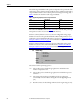
Table Of Contents
- Front Cover
- Important User Information
- Summary of Changes
- Table of Contents
- Introduction
- About the Drive
- Identifying the Drive by Cabinet Assembly ID Number
- LiquiFlo 2.0 Drive Component Locations
- Identifying the Power Module by Model Number
- AC Line I/O Board Description (Frame 3 Only)
- Standard I/O Board Description (Frame 3 Only)
- Combined I/O Board Description (Frame 4 Only)
- DPI Communication Ports
- Optional Equipment
- Planning the Installation
- Mounting The Power Module and Grounding the Drive
- Installing Input and Output Power Wiring
- Completing the Installation
- Using the Start-up Routines
- Programming Basics
- Parameter Descriptions
- Troubleshooting the Drive
- Verify that the DC Bus Capacitors are Discharged Before Servicing the Drive
- Determining Drive Status Using the Status LEDs
- About Alarms
- About Faults
- Diagnostic Parameters
- Common Symptoms and Corrective Actions
- Replacement Parts
- Board Replacement, Firmware Setup Procedures
- Troubleshooting the Drive Using the OIM
- Checking the Power Modules with Input Power Off
- Technical Specifications
- Using the OIM
- Installing and Removing the OIM
- Display Description
- OIM Menu Structure
- Powering Up and Adjusting the OIM
- Selecting a Device in the System
- Using the OIM to Program the Drive
- Monitoring the Drive Using the Process Display Screen on the OIM
- Displaying and Changing the OIM Reference
- Customizing the Process Display Screen
- Customizing the Function Keys
- Controlling the Drive From the OIM
- LiquiFlo 2.0 Drive Frame 3 Wiring Diagrams
- LiquiFlo 2.0 Drive Frame 4 Wiring Diagrams
- Index
- Back Cover
76 Rockwell Automation Publication D2-3518-3 - May 2013
Chapter 9
The usable range and default for this parameter depends on the operational mode
of the analog output, which in turn depends both on the capabilities of the analog
output hardware and the current value of parameter Analog Out Config (340).
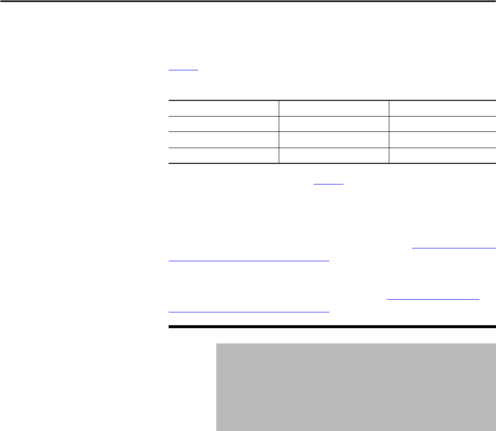
Tab le 6
describes the details for usable range and default.
Table 6 - Appl Analog Output (31) usable range and default
The value in the Default column of Ta b le 6 is in effect when the drive powers up.
This parameter value is not stored in non-volatile memory.
For frame 3 drives (firmware version 1.x), the user-configurable analog output
hardware is located on the optional Standard I/O Board. This parameter is not
usable if the optional Standard I/O Board is not present. See Standard I/O Board
Description (Frame 3 Only) on page 27 for terminal block assignments.
For frame 4 drives (firmware version 2.x), the user-configurable analog output
hardware is located on the Combined I/O Board. See Combined I/O Board
Description (Frame 4 Only) on page 29 for terminal block assignments.
Selects how rectifier sequencing operates.
Mode Usable Range Default
0...10V (unipolar) 0.000...10.000V 0.000V
-10...10V (bipolar) -10.000...10.000V 0.000V
4...20 mA 0.000...20.000 mA 0.000 mA
32 Rctfr Config
Range: 0 = Run at Start
1 = Run at Power Up
2 = Manual Control
3 = Diode Rectifier
Default: 0
Access: 1 Path: Monitor > Application
See also: 30
0 = The precharge is closed and voltage regulation is enabled when the
inverter is requested to start.
1 = The precharge is closed and voltage regulation is enabled when power is
turned on.
2 = The closing of the precharge and enabling of voltage regulation is
controlled by some other device writing into inverter Appl Digital Out
(30).
3 = Rectifier consists of a diode bridge. This mode is for engineering use only.