
Owner's manual
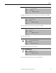
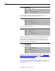
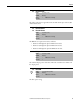
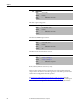
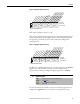
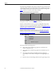
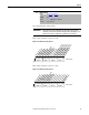
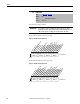
Table Of Contents
- Front Cover
- Important User Information
- Summary of Changes
- Table of Contents
- Introduction
- About the Drive
- Identifying the Drive by Cabinet Assembly ID Number
- LiquiFlo 2.0 Drive Component Locations
- Identifying the Power Module by Model Number
- AC Line I/O Board Description (Frame 3 Only)
- Standard I/O Board Description (Frame 3 Only)
- Combined I/O Board Description (Frame 4 Only)
- DPI Communication Ports
- Optional Equipment
- Planning the Installation
- Mounting The Power Module and Grounding the Drive
- Installing Input and Output Power Wiring
- Completing the Installation
- Using the Start-up Routines
- Programming Basics
- Parameter Descriptions
- Troubleshooting the Drive
- Verify that the DC Bus Capacitors are Discharged Before Servicing the Drive
- Determining Drive Status Using the Status LEDs
- About Alarms
- About Faults
- Diagnostic Parameters
- Common Symptoms and Corrective Actions
- Replacement Parts
- Board Replacement, Firmware Setup Procedures
- Troubleshooting the Drive Using the OIM
- Checking the Power Modules with Input Power Off
- Technical Specifications
- Using the OIM
- Installing and Removing the OIM
- Display Description
- OIM Menu Structure
- Powering Up and Adjusting the OIM
- Selecting a Device in the System
- Using the OIM to Program the Drive
- Monitoring the Drive Using the Process Display Screen on the OIM
- Displaying and Changing the OIM Reference
- Customizing the Process Display Screen
- Customizing the Function Keys
- Controlling the Drive From the OIM
- LiquiFlo 2.0 Drive Frame 3 Wiring Diagrams
- LiquiFlo 2.0 Drive Frame 4 Wiring Diagrams
- Index
- Back Cover

74 Rockwell Automation Publication D2-3518-3 - May 2013
Chapter 9
The drive output voltage class.
The drive rated RMS output current.
The Main Control board software version.
Frame 3 drives (firmware version 1.x) only:
The lower byte of this parameter controls the state of the application digital
outputs on the AC Line I/O card. The upper byte controls the operation of the
rectifier when configured for manual operation.
See AC Line I/O Board Description (Frame 3 Only)
on page 25 through
Combined I/O Board Description (Frame 4 Only)
on page 29 for a description
of I/O hardware that is present on this drive and is controlled by the inverter.
27 Rated Volts
Range: 480V [0.1V AC]
Default: Read Only
Access: 1 Path: Monitor > Drive Data
See also:
28 Rated Amps
Range: 0.0...6553.5 Amps [0.1 A]
Default: Read Only
Access: 1 Path: Monitor > Drive Data
See also:
29 Control SW Ver
Range: 0.000...65.256 [0.001]
Default: Read Only
Access: 1 Path: Monitor > Drive Data
See also: 196
30 Appl Digital Out
Range: See Figure 30 and Figure 31
Default: See Figure 30 and Figure 31
Access: 1 Path: Monitor > Application
See also: