
Owner's manual
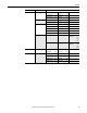

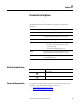
Table Of Contents
- Front Cover
- Important User Information
- Summary of Changes
- Table of Contents
- Introduction
- About the Drive
- Identifying the Drive by Cabinet Assembly ID Number
- LiquiFlo 2.0 Drive Component Locations
- Identifying the Power Module by Model Number
- AC Line I/O Board Description (Frame 3 Only)
- Standard I/O Board Description (Frame 3 Only)
- Combined I/O Board Description (Frame 4 Only)
- DPI Communication Ports
- Optional Equipment
- Planning the Installation
- Mounting The Power Module and Grounding the Drive
- Installing Input and Output Power Wiring
- Completing the Installation
- Using the Start-up Routines
- Programming Basics
- Parameter Descriptions
- Troubleshooting the Drive
- Verify that the DC Bus Capacitors are Discharged Before Servicing the Drive
- Determining Drive Status Using the Status LEDs
- About Alarms
- About Faults
- Diagnostic Parameters
- Common Symptoms and Corrective Actions
- Replacement Parts
- Board Replacement, Firmware Setup Procedures
- Troubleshooting the Drive Using the OIM
- Checking the Power Modules with Input Power Off
- Technical Specifications
- Using the OIM
- Installing and Removing the OIM
- Display Description
- OIM Menu Structure
- Powering Up and Adjusting the OIM
- Selecting a Device in the System
- Using the OIM to Program the Drive
- Monitoring the Drive Using the Process Display Screen on the OIM
- Displaying and Changing the OIM Reference
- Customizing the Process Display Screen
- Customizing the Function Keys
- Controlling the Drive From the OIM
- LiquiFlo 2.0 Drive Frame 3 Wiring Diagrams
- LiquiFlo 2.0 Drive Frame 4 Wiring Diagrams
- Index
- Back Cover

Rockwell Automation Publication D2-3518-3 - May 2013 61
Chapter 8
Utility Drive Memory Param Access Lvl 196 Save to User Set 199 Drive Checksum 203
Reset to Defaults 197 Reset Meters 200 –
Load Frm Usr Set 198 Language 201 –
Status Drive Alarm 211 Dig In Status 216 –
Start Inhibits 214 Dig Out Status 217 –
Diagnostics Fault Frequency 220 Fault Amps D 225 Testpoint 1 Data 235
Fault Amps R 221 Fault Volts Vdc 226 Testpoint 2 Sel 236
Fault Amps S 222 Fault Volts Q 227 Testpoint 2 Data 237
Fault Amps T 223 Fault Volts D 228 –
Fault Amps Q 224 Testpoint 1 Sel 234 –
Fault Queue Fault Config 238 Fault To Invertr 241 Fault 1 Code...
Fault 4 Code
243
245
247
249
Fault Clear 240 Power Up Marker 242 Fault 1 Time...
Fault 4 Time
244
246
248
250
Communications In Data Links IOC Redir Time 300 Service 302 302 –
IOC Redir Max 301 Service 303 303 –
Inputs & Outputs Temperatures etc Rct IGBT Tmp Top 345 Rct Coldplt Tmp 349 Rct PS -12V 353
Rct IGBT Tmp Up 346 Rct Ambient Tmp 350 Rct I/O ID V 354
Rct IGBT Tmp Low 347 Rct PS Tmp 351 –
Rct IGBT Tmp Bot 348 Rct PS +12V 352 –
File Group Parameters