
Owner's manual
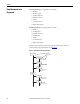
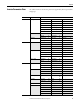
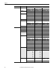
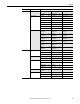
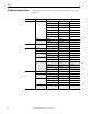
Table Of Contents
- Front Cover
- Important User Information
- Summary of Changes
- Table of Contents
- Introduction
- About the Drive
- Identifying the Drive by Cabinet Assembly ID Number
- LiquiFlo 2.0 Drive Component Locations
- Identifying the Power Module by Model Number
- AC Line I/O Board Description (Frame 3 Only)
- Standard I/O Board Description (Frame 3 Only)
- Combined I/O Board Description (Frame 4 Only)
- DPI Communication Ports
- Optional Equipment
- Planning the Installation
- Mounting The Power Module and Grounding the Drive
- Installing Input and Output Power Wiring
- Completing the Installation
- Using the Start-up Routines
- Programming Basics
- Parameter Descriptions
- Troubleshooting the Drive
- Verify that the DC Bus Capacitors are Discharged Before Servicing the Drive
- Determining Drive Status Using the Status LEDs
- About Alarms
- About Faults
- Diagnostic Parameters
- Common Symptoms and Corrective Actions
- Replacement Parts
- Board Replacement, Firmware Setup Procedures
- Troubleshooting the Drive Using the OIM
- Checking the Power Modules with Input Power Off
- Technical Specifications
- Using the OIM
- Installing and Removing the OIM
- Display Description
- OIM Menu Structure
- Powering Up and Adjusting the OIM
- Selecting a Device in the System
- Using the OIM to Program the Drive
- Monitoring the Drive Using the Process Display Screen on the OIM
- Displaying and Changing the OIM Reference
- Customizing the Process Display Screen
- Customizing the Function Keys
- Controlling the Drive From the OIM
- LiquiFlo 2.0 Drive Frame 3 Wiring Diagrams
- LiquiFlo 2.0 Drive Frame 4 Wiring Diagrams
- Index
- Back Cover
60 Rockwell Automation Publication D2-3518-3 - May 2013
Chapter 8
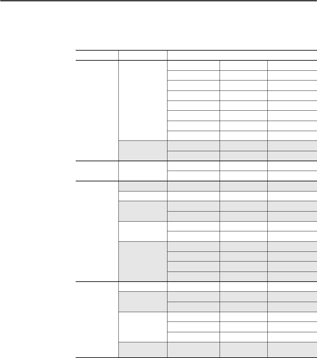
Rectifier Parameters View
The table below shows the rectifier parameters organized by their respective files
and groups.
File Group Parameters
Monitor Metering Line Frequency 1 Input Voltage TR 9 Elapsed Run Time 17
Input Current R 2 DC Bus Voltage 10 Rctfr Base Temp 18
Input Current S 3 Active Voltage 11 Rctfr IGBT Temp 19
Input Current T 4 Reactive Voltage 12 Rctfr IT Overld 20
Active Current 5 Input kW 13 Rctfr I2T Overld 21
Reactive Current 6 Input Pwr Factor 14 Line I Imbalance 22
Input Voltage RS 7 Motoring kWh 15 Line V Imbalance 23
Input Voltage ST 8 Regen kWh 16 –
Drive Data Rated kW 26 Rated Amps 28 –
Rated Volts 27 Control SW Ver 29 –
Configuration AC Line V Imbalance Lmt 60 I Imbalance Lmt 62 Ride Through Ena 64
V Imbalance Time 61 I Imbalance Time 63 Ride Through Sec 65
Dynamic Control Control and Status Rectifier Contrl 100 Rectifier Status 101 –
Bus Voltage Vdc Optimize 102 Vdc Reference 103 Vdc Command 104
Load Limits Current Limit 105 Max Motor Volts 107 Base Motor Freq 109
Input Load Amps 106 Max Motor Freq 108 –
Regulator Tuning VML Ki 110 CML Ki 112 VML Reset Level 114
VML Kp 111 CML Kp 113 –
Cold Plate Cold Plate Temp 120 CPC K2 124 Delay After Move 128
Invtr Base Temp 121 High Temp Limit 125 Ambient Temp 129
Rctfr Base Temp 122 Low Temp Limit 126 –
CPC K1 123 Start Move Time 127 –
Internal Data Normalized Amps Input Load Amps 150 Current Limit 151 –
Total Elapsed Life KW H 152 Life Power Time 154 –
Life Run Time 153 Life Power Cycle 155 –
DPI Counters DPI Error 156 CS Timeout Cnt 159 PC MSG Tx Cnt 162
CS Msg Rx Cnt 157 CS MSG Bad Cnt 160 PC Timeout Cnt 163
CS Msg Tx Cnt 158 PC MSG Rx Cnt 161 CAN Bus Off Cnt 164
D/A Output Sel D/A Select (N) 171...
174
– –