
Owner's manual
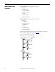
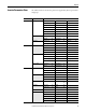
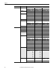
Table Of Contents
- Front Cover
- Important User Information
- Summary of Changes
- Table of Contents
- Introduction
- About the Drive
- Identifying the Drive by Cabinet Assembly ID Number
- LiquiFlo 2.0 Drive Component Locations
- Identifying the Power Module by Model Number
- AC Line I/O Board Description (Frame 3 Only)
- Standard I/O Board Description (Frame 3 Only)
- Combined I/O Board Description (Frame 4 Only)
- DPI Communication Ports
- Optional Equipment
- Planning the Installation
- Mounting The Power Module and Grounding the Drive
- Installing Input and Output Power Wiring
- Completing the Installation
- Using the Start-up Routines
- Programming Basics
- Parameter Descriptions
- Troubleshooting the Drive
- Verify that the DC Bus Capacitors are Discharged Before Servicing the Drive
- Determining Drive Status Using the Status LEDs
- About Alarms
- About Faults
- Diagnostic Parameters
- Common Symptoms and Corrective Actions
- Replacement Parts
- Board Replacement, Firmware Setup Procedures
- Troubleshooting the Drive Using the OIM
- Checking the Power Modules with Input Power Off
- Technical Specifications
- Using the OIM
- Installing and Removing the OIM
- Display Description
- OIM Menu Structure
- Powering Up and Adjusting the OIM
- Selecting a Device in the System
- Using the OIM to Program the Drive
- Monitoring the Drive Using the Process Display Screen on the OIM
- Displaying and Changing the OIM Reference
- Customizing the Process Display Screen
- Customizing the Function Keys
- Controlling the Drive From the OIM
- LiquiFlo 2.0 Drive Frame 3 Wiring Diagrams
- LiquiFlo 2.0 Drive Frame 4 Wiring Diagrams
- Index
- Back Cover
Rockwell Automation Publication D2-3518-3 - May 2013 59
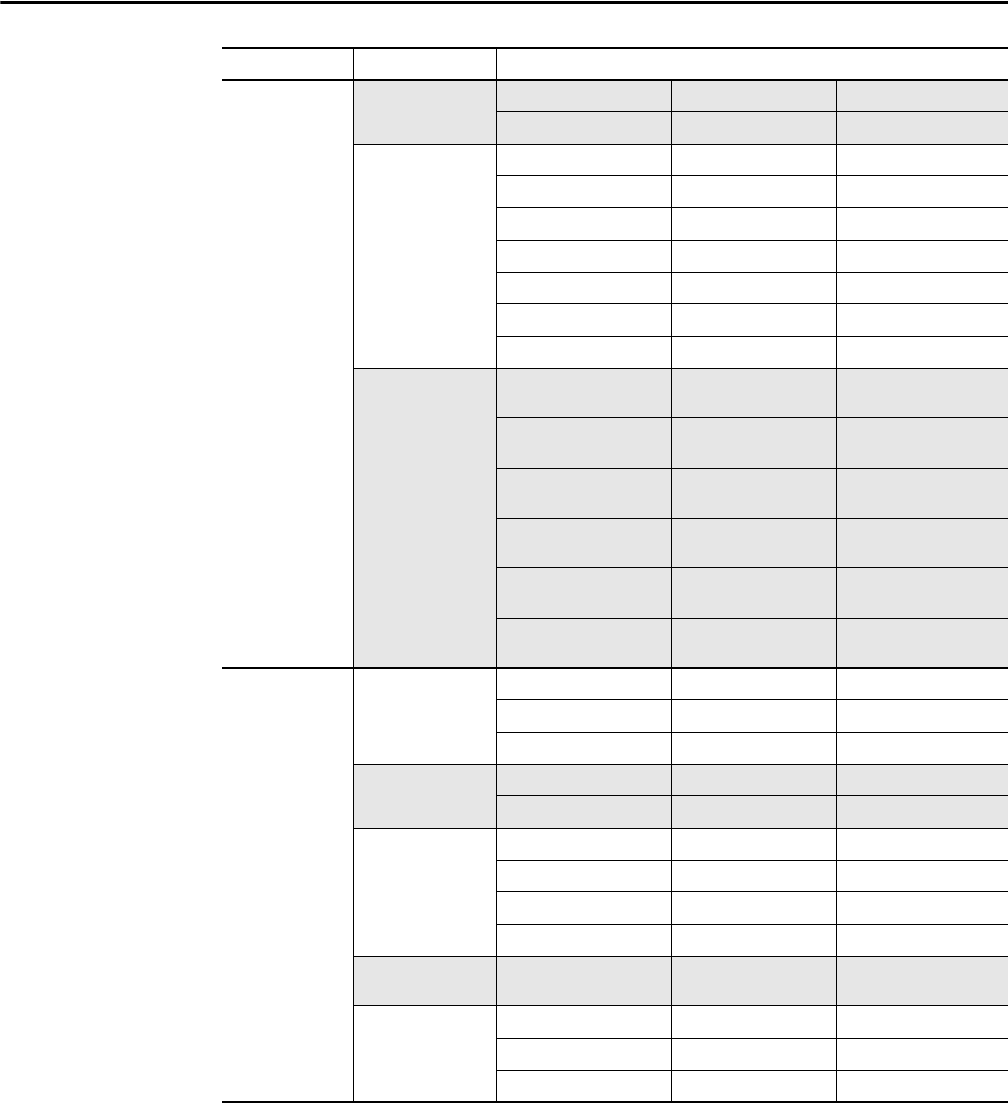
Chapter 8
Communication Comm Control DPI Data Rate 270 Drive Ref Rslt 272 –
Drive Logic Rslt 271 Drive Ramp Rslt 273 –
Masks & Owners Logic Mask 276 Fault Clr Mask 283 Reference Owner 292
Start Mask 277 MOP Mask 284 Accel Owner 293
Jog Mask 278 Local Mask 285 Decel Owner 294
Direction Mask 279 Stop Owner 288 Fault Clr Owner 295
Reference Mask 280 Start Owner 289 MOP Owner 296
Accel Mask 281 Jog Owner 290 Local Owner 297
Decel Mask 282 Direction Owner 291 –
Datalinks Data In A1 -
Link A Word 1
300 Data In D 1 -
Link D Word 1
306 Data Out C 1 -
Link C Word 1
314
Data In A2 -
Link A Word 2
301 Data In D 2 -
Link D Word 2
307 Data Out C 2 -
Link C Word 2
315
Data In B 1 -
Link B Word 1
302 Data Out A1 -
Link A Word 1
310 Data Out D 1 -
Link D Word 1
316
Data In B 2 -
Link B Word 2
303 Data Out A2 -
Link A Word 2
311 Data Out D 2 -
Link D Word 2
317
Data In C 1 -
Link C Word 1
304 Data Out B 1 -
Link B Word 1
312 –
Data In C 2 -
Link C Word 2
305 Data Out B 2 -
Link B Word 2
313 –
Inputs & Outputs Analog Inputs Anlg In Config 320 Analog In 1 Lo 323 Analog In 2 Lo 326
Anlg In Sqr Root 321 Analog In 1 Loss 324 Analog In 2 Loss 327
Analog In 1 Hi 322 Analog In 2 Hi 325 –
Analog Outputs Anlg Out Config 340 Analog Out1 Sel 342 Analog Out1 Lo 344
Anlg Out Absolut 341 Analog Out1 Hi 343 –
Temperature etc Inv IGBT Tmp Top 345 Inv Coldplt Tmp 349 Inv PS -12 353
Inv IGBT Tmp Up 346 Inv Ambient Tmp 350 Inv I/O ID V 354
Inv IGBT TMP Low 347 Inv PS Tmp 351 –
Inv IGBT Tmp Bot 348 Inv PS +12 352 –
Digital Inputs Digital In1 Sel...
Digital In6 Sel
361...
366
– –
Digital Outputs Digital Out1 Sel 380 Dig Out1 OffTime 383 Dig Out2 OnTime 386
Dig Out1 Level 381 Digital Out2 Sel 384 Dig Out2 OffTime 387
Dig Out1 OnTime 382 Dig Out2 Level 385 –
File Group Parameters