
Owner's manual
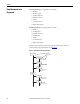
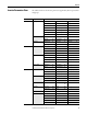
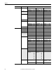
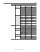
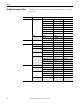
Table Of Contents
- Front Cover
- Important User Information
- Summary of Changes
- Table of Contents
- Introduction
- About the Drive
- Identifying the Drive by Cabinet Assembly ID Number
- LiquiFlo 2.0 Drive Component Locations
- Identifying the Power Module by Model Number
- AC Line I/O Board Description (Frame 3 Only)
- Standard I/O Board Description (Frame 3 Only)
- Combined I/O Board Description (Frame 4 Only)
- DPI Communication Ports
- Optional Equipment
- Planning the Installation
- Mounting The Power Module and Grounding the Drive
- Installing Input and Output Power Wiring
- Completing the Installation
- Using the Start-up Routines
- Programming Basics
- Parameter Descriptions
- Troubleshooting the Drive
- Verify that the DC Bus Capacitors are Discharged Before Servicing the Drive
- Determining Drive Status Using the Status LEDs
- About Alarms
- About Faults
- Diagnostic Parameters
- Common Symptoms and Corrective Actions
- Replacement Parts
- Board Replacement, Firmware Setup Procedures
- Troubleshooting the Drive Using the OIM
- Checking the Power Modules with Input Power Off
- Technical Specifications
- Using the OIM
- Installing and Removing the OIM
- Display Description
- OIM Menu Structure
- Powering Up and Adjusting the OIM
- Selecting a Device in the System
- Using the OIM to Program the Drive
- Monitoring the Drive Using the Process Display Screen on the OIM
- Displaying and Changing the OIM Reference
- Customizing the Process Display Screen
- Customizing the Function Keys
- Controlling the Drive From the OIM
- LiquiFlo 2.0 Drive Frame 3 Wiring Diagrams
- LiquiFlo 2.0 Drive Frame 4 Wiring Diagrams
- Index
- Back Cover

58 Rockwell Automation Publication D2-3518-3 - May 2013
Chapter 8
Dynamic Control Ramp Rates Accel Time 1 140 Decel Time 1 142 S Curve % 146
Accel Time 2 141 Decel Time 2 143 –
Load Limits Current Lmt Sel 147 Current Lmt Gain 149 PWM Frequency 151
Current Lmt Val 148 Drive OL Mode 150 –
Stop/Brake Modes Stop Mode A 155 DC Brake Time 159 DB Resistor Type 163
Stop Mode B 156 Bus Reg Ki 160 Bus Reg Kp 164
DC Brake Lvl Sel 157 Bus Reg Mode A 161 Bus Reg Kd 165
DC Brake Level 158 Bus Reg Mode B 162 –
Stop/Restart Modes Start At PowerUp 168 Flying Start En 169 –
Restart Modes Flying Start Gain 170 Sleep-Wake
Mode
178 Wake Time 181
Auto Rstrt Tries 174 Sleep-Wake Ref 179 Sleep Level 182
Auto Rstrt Delay 175 Wake Level 180 Sleep Time 183
Power Loss Power Loss Mode 184 Power Loss Time 185 Power Loss Level 186
Utility Direction Config Direction Mode 190 – – –
HIM Ref Config Save HIM Ref 192 Man Ref Preload 193 –
MOP Config Save MOP Ref 194 MOP Rate 195 –
Drive Memory Param Access Lvl 196 Save To User Set 199 Voltage Class 202
Reset To Defalts 197 Reset Meters 200 Drive Checksum 203
Load Frm Usr Set 198 Language 201 –
Diagnostics Drive Status 1 209 Dig Out Status 217 Status 1 @ Fault 227
Drive Status 2 210 Invtr Base Temp 218 Status 2 @ Fault 228
Drive Alarm 1 211 Drive OL Count 219 Alarm 1 @ Fault 229
Drive Alarm 2 212 Motor OL Count 220 Alarm 2 @ Fault 230
Speed Ref Source 213 Imbalance Count 221 Testpoint 1 Sel 234
Start Inhibits 214 Fault Frequency 224 Testpoint 1 Data 235
Last Stop Source 215 Fault Amps 225 Testpoint 2 Sel 236
Dig In Status 216 Fault Bus Volts 226 Testpoint 2 Data 237
Faults Fault Config 1 238 Fault Clear Mode 241 –
Fault Clear 240 Power Up Marker 242 –
Fault 1 Code...
Fault 8 Code
243
245
247
249
251
253
255
257
Fault 1 Time...
Fault 8 Time
244
246
248
250
252
254
256
258
–
Alarms Alarm Config 1 259 Alarm Clear 261 Alarm 1 Code...
Alarm 8 Code
262...
269
Drive Alarm 1 211 Drive Alarm 2 212 –
File Group Parameters