
Owner's manual
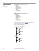
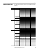
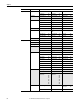
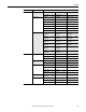
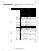
Table Of Contents
- Front Cover
- Important User Information
- Summary of Changes
- Table of Contents
- Introduction
- About the Drive
- Identifying the Drive by Cabinet Assembly ID Number
- LiquiFlo 2.0 Drive Component Locations
- Identifying the Power Module by Model Number
- AC Line I/O Board Description (Frame 3 Only)
- Standard I/O Board Description (Frame 3 Only)
- Combined I/O Board Description (Frame 4 Only)
- DPI Communication Ports
- Optional Equipment
- Planning the Installation
- Mounting The Power Module and Grounding the Drive
- Installing Input and Output Power Wiring
- Completing the Installation
- Using the Start-up Routines
- Programming Basics
- Parameter Descriptions
- Troubleshooting the Drive
- Verify that the DC Bus Capacitors are Discharged Before Servicing the Drive
- Determining Drive Status Using the Status LEDs
- About Alarms
- About Faults
- Diagnostic Parameters
- Common Symptoms and Corrective Actions
- Replacement Parts
- Board Replacement, Firmware Setup Procedures
- Troubleshooting the Drive Using the OIM
- Checking the Power Modules with Input Power Off
- Technical Specifications
- Using the OIM
- Installing and Removing the OIM
- Display Description
- OIM Menu Structure
- Powering Up and Adjusting the OIM
- Selecting a Device in the System
- Using the OIM to Program the Drive
- Monitoring the Drive Using the Process Display Screen on the OIM
- Displaying and Changing the OIM Reference
- Customizing the Process Display Screen
- Customizing the Function Keys
- Controlling the Drive From the OIM
- LiquiFlo 2.0 Drive Frame 3 Wiring Diagrams
- LiquiFlo 2.0 Drive Frame 4 Wiring Diagrams
- Index
- Back Cover
Rockwell Automation Publication D2-3518-3 - May 2013 57
Chapter 8
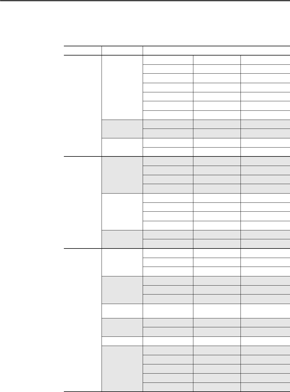
Inverter Parameters View
The table below shows the inverter parameters organized by their respective files
and groups.
File Group Parameters
Monitor Metering Output Freq 1 Output Powr Fctr 8 Analog In2 Value 17
Commanded Freq 2 Elapsed MWh 9 Analog In3 Value 18
Output Current 3 Elapsed Run Time 10 Ground Current 21
Torque Current 4 MOP Frequency 11 Phase U Current 22
Flux Current 5 DC Bus Voltage 12 Phase V Current 23
Output Voltage 6 DC Bus Memory 13 Phase W Current 24
Output Power 7 Analog In1 Value 16 Est Input Power 25
Drive Data Rated kW 26 Rated Amps 28 –
Rated Volts 27 Control SW Ver 29 –
Application Appl Digital Out 30 Rctfr Config 32 Rctfr Status 34
Appl Analog Out 31 Rctfr Control 33 Rctfr Fault 35
Motor Control
Motor Data Motor Type 40 Motor NP RPM 44 Motor OL Amps 48
Motor NP Volts 41 Motor NP Power 45 Imbalance Limit 49
Motor NP FLA 42 Mtr NP Pwr Units 46 Imbalance Time 50
Motor NP Hertz 43 Motor OL Hertz 47 –
Torq Attributes Torque Perf Mode 53 Flux Up Mode 57 IR Voltage Drop 62
Maximum Voltage 54 Flux Up Time 58 Flux Current Ref 63
Maximum Freq 55 SV Boost Filter 59 Ixo Voltage Drop 64
Compensation 56 Autotune 61 –
Volts per Hertz Start/Acc Boost 69 Break Voltage 71 –
Run Boost 70 Break Frequency 72 –
Speed Command Spd Mode & Limits Speed Mode 80 Overspeed Limit 83 Skip Frequency 3 86
Minimum Speed 81 Skip Frequency 1 84 Skip Freq Band 87
Maximum Speed 82 Skip Frequency 2 85 –
Speed References Speed Ref A Sel 90 Speed Ref B Sel 93 TB Man Ref Sel 96
Speed Ref A Hi 91 Speed Ref B Hi 94 TB Man Ref Hi 97
Speed Ref A Lo 92 Speed Ref B Lo 95 TB Man Ref Lo 98
Discrete Speeds Jog Speed 100 Preset Speed 1...7 101...
107
–
Speed Trim Trim In Select 117 Trim Hi 119 –
Trim Out Select 118 Trim Lo 120 –
Slip Comp Slip RPM @ FLA 121 Slip Comp Gain 122 Slip RPM Meter 123
Process PI PI Configuration 124 PI Integral Time 129 PI Status 134
PI Control 125 PI Prop Gain 130 PI Ref Meter 135
PI Reference Sel 126 PI Lower Limit 131 PI Fdback Meter 136
PI Setpoint 127 PI Upper Limit 132 PI Error Meter 137
PI Feedback Sel 128 PI Preload 133 PI Output Meter 138