
Owner's manual
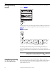
Table Of Contents
- Front Cover
- Important User Information
- Summary of Changes
- Table of Contents
- Introduction
- About the Drive
- Identifying the Drive by Cabinet Assembly ID Number
- LiquiFlo 2.0 Drive Component Locations
- Identifying the Power Module by Model Number
- AC Line I/O Board Description (Frame 3 Only)
- Standard I/O Board Description (Frame 3 Only)
- Combined I/O Board Description (Frame 4 Only)
- DPI Communication Ports
- Optional Equipment
- Planning the Installation
- Mounting The Power Module and Grounding the Drive
- Installing Input and Output Power Wiring
- Completing the Installation
- Using the Start-up Routines
- Programming Basics
- Parameter Descriptions
- Troubleshooting the Drive
- Verify that the DC Bus Capacitors are Discharged Before Servicing the Drive
- Determining Drive Status Using the Status LEDs
- About Alarms
- About Faults
- Diagnostic Parameters
- Common Symptoms and Corrective Actions
- Replacement Parts
- Board Replacement, Firmware Setup Procedures
- Troubleshooting the Drive Using the OIM
- Checking the Power Modules with Input Power Off
- Technical Specifications
- Using the OIM
- Installing and Removing the OIM
- Display Description
- OIM Menu Structure
- Powering Up and Adjusting the OIM
- Selecting a Device in the System
- Using the OIM to Program the Drive
- Monitoring the Drive Using the Process Display Screen on the OIM
- Displaying and Changing the OIM Reference
- Customizing the Process Display Screen
- Customizing the Function Keys
- Controlling the Drive From the OIM
- LiquiFlo 2.0 Drive Frame 3 Wiring Diagrams
- LiquiFlo 2.0 Drive Frame 4 Wiring Diagrams
- Index
- Back Cover
54 Rockwell Automation Publication D2-3518-3 - May 2013
Chapter 7
Running the Start-up
Routines
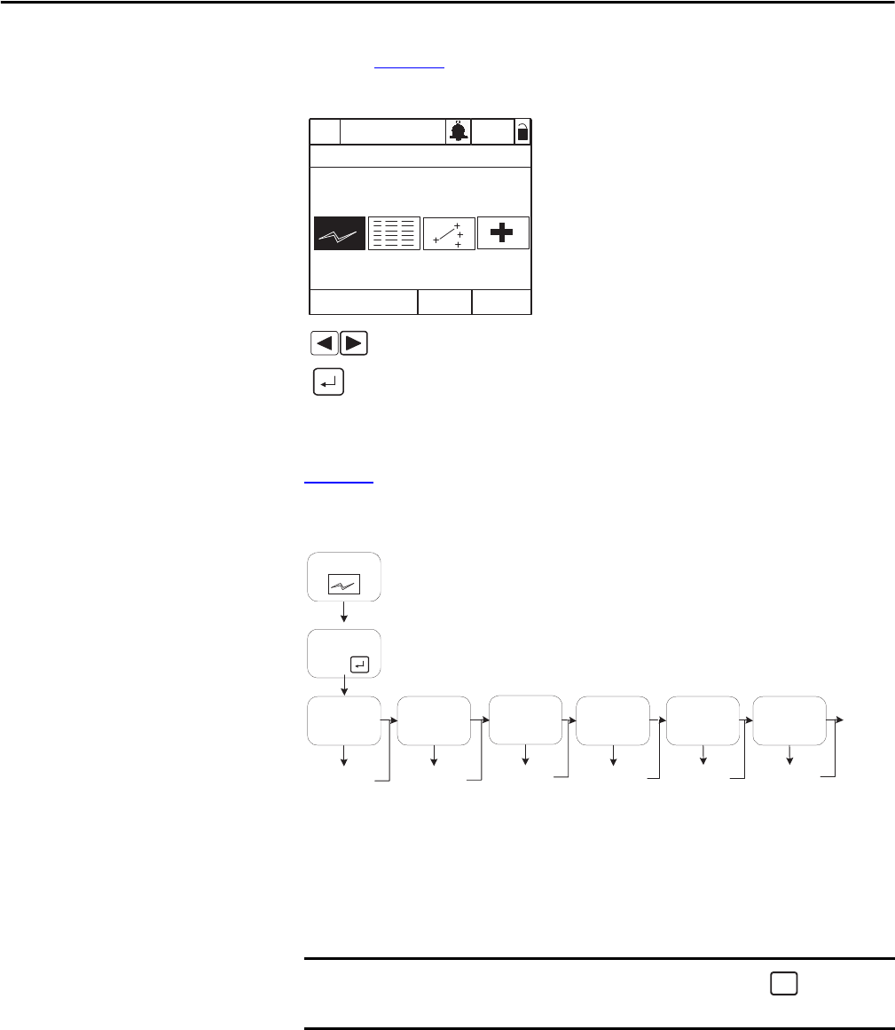
To access the start-up routines, select the Start-Up icon from the main menu as
shown in Figure 23
Figure 23 - Accessing the Start-Up Routines
The Start-Up menu screen contains eight selections. The first seven menu items
contain the most commonly used parameters associated with each function. See
Figure 24
.
Figure 24 - Start-Up Menu
The Start-up routine automates the process of entering values of selected
parameters by taking you to the next parameter after you accept a parameter
value. As each item in the list is completed, you are automatically advanced to the
next step.
Exiting Before Completing
the Start-Up Routines
To exit the Start-up routines, press the F4 key (Exit). When you select the
Start-up icon from the main menu again, you are prompted to either continue or
restart the Start-up routines. If you select Continue, you are returned to the
point at which you exited.
IMPORTANT
Parameter values are saved as they are changed. Pressing or aborting the
Start-up routine does not undo the changes.
Lang
P0: LiquiFlo 2.0
Auto
Stopped
Main Menu
Start-Up
Highlight Start-Up icon
Select
Monitor
>>
Start-Up
Main Menu
Input
Voltage
Motor
Data
Motor
Tests
Speed
Limits
Ref Setup
Configure
I/O
Configure for
Alternate
Input Voltage
Enter Motor
Nameplate
Data
Optimize
Torque and
Verify Direction
Set Min/Max
Speed, Stop
Mode, and
Direction Conrol
Done
Set
Reference
Control
Source
Set TB I/O
Functions
Intro
Press
ESC/
PROG