
Owner's manual
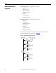
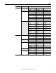
Table Of Contents
- Front Cover
- Important User Information
- Summary of Changes
- Table of Contents
- Introduction
- About the Drive
- Identifying the Drive by Cabinet Assembly ID Number
- LiquiFlo 2.0 Drive Component Locations
- Identifying the Power Module by Model Number
- AC Line I/O Board Description (Frame 3 Only)
- Standard I/O Board Description (Frame 3 Only)
- Combined I/O Board Description (Frame 4 Only)
- DPI Communication Ports
- Optional Equipment
- Planning the Installation
- Mounting The Power Module and Grounding the Drive
- Installing Input and Output Power Wiring
- Completing the Installation
- Using the Start-up Routines
- Programming Basics
- Parameter Descriptions
- Troubleshooting the Drive
- Verify that the DC Bus Capacitors are Discharged Before Servicing the Drive
- Determining Drive Status Using the Status LEDs
- About Alarms
- About Faults
- Diagnostic Parameters
- Common Symptoms and Corrective Actions
- Replacement Parts
- Board Replacement, Firmware Setup Procedures
- Troubleshooting the Drive Using the OIM
- Checking the Power Modules with Input Power Off
- Technical Specifications
- Using the OIM
- Installing and Removing the OIM
- Display Description
- OIM Menu Structure
- Powering Up and Adjusting the OIM
- Selecting a Device in the System
- Using the OIM to Program the Drive
- Monitoring the Drive Using the Process Display Screen on the OIM
- Displaying and Changing the OIM Reference
- Customizing the Process Display Screen
- Customizing the Function Keys
- Controlling the Drive From the OIM
- LiquiFlo 2.0 Drive Frame 3 Wiring Diagrams
- LiquiFlo 2.0 Drive Frame 4 Wiring Diagrams
- Index
- Back Cover

Rockwell Automation Publication D2-3518-3 - May 2013 51
Chapter 6
Completing the Installation
This chapter provides instructions on how to perform a final check of the
installation before power is applied to the drive.
Checking the Installation
Use the following procedure to verify the condition of the installation:
1. Turn off, lock out, and tag the input power to the drive. Wait 5 minutes.
2. Verify that the DC bus voltage is zero. See Verify that the DC Bus
Capacitors are Discharged Before Servicing the Drive on page 195.
3. Remove any debris, such as metal shavings, from around the drive.
4. Check that there is adequate clearance around the drive.
5. Verify that the wiring to the terminal strip and the power terminals is
correct.
6. Check that the wire size is within terminal specifications and that the wires
are tightened properly.
7. Check that user-supplied branch circuit protection is installed and
correctly rated.
ATTENTION: Only qualified electrical personnel familiar with the construction
and operation of this equipment and the hazards involved should start and
adjust it. Read and understand this manual in its entirety before proceeding.
Failure to observe this precaution could result in severe bodily injury or loss of
life.
ATTENTION: DC bus capacitors retain hazardous voltages after input power has
been disconnected. After disconnecting input power, wait 5 minutes for the DC
bus capacitors to discharge and then check the voltage with a voltmeter to
ensure the DC bus capacitors are discharged before touching any internal
components. Failure to observe this precaution could result in severe bodily
injury or loss of life.
ATTENTION: You must provide an external, hardwired emergency stop circuit
outside of the drive circuitry. This circuit must disable the system in case of
improper operation. Uncontrolled machine operation may result if this
procedure is not followed. Failure to observe this precaution could result in
bodily injury.