
Owner's manual
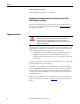
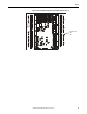

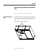
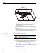
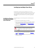
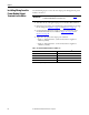
Table Of Contents
- Front Cover
- Important User Information
- Summary of Changes
- Table of Contents
- Introduction
- About the Drive
- Identifying the Drive by Cabinet Assembly ID Number
- LiquiFlo 2.0 Drive Component Locations
- Identifying the Power Module by Model Number
- AC Line I/O Board Description (Frame 3 Only)
- Standard I/O Board Description (Frame 3 Only)
- Combined I/O Board Description (Frame 4 Only)
- DPI Communication Ports
- Optional Equipment
- Planning the Installation
- Mounting The Power Module and Grounding the Drive
- Installing Input and Output Power Wiring
- Completing the Installation
- Using the Start-up Routines
- Programming Basics
- Parameter Descriptions
- Troubleshooting the Drive
- Verify that the DC Bus Capacitors are Discharged Before Servicing the Drive
- Determining Drive Status Using the Status LEDs
- About Alarms
- About Faults
- Diagnostic Parameters
- Common Symptoms and Corrective Actions
- Replacement Parts
- Board Replacement, Firmware Setup Procedures
- Troubleshooting the Drive Using the OIM
- Checking the Power Modules with Input Power Off
- Technical Specifications
- Using the OIM
- Installing and Removing the OIM
- Display Description
- OIM Menu Structure
- Powering Up and Adjusting the OIM
- Selecting a Device in the System
- Using the OIM to Program the Drive
- Monitoring the Drive Using the Process Display Screen on the OIM
- Displaying and Changing the OIM Reference
- Customizing the Process Display Screen
- Customizing the Function Keys
- Controlling the Drive From the OIM
- LiquiFlo 2.0 Drive Frame 3 Wiring Diagrams
- LiquiFlo 2.0 Drive Frame 4 Wiring Diagrams
- Index
- Back Cover

50 Rockwell Automation Publication D2-3518-3 - May 2013
Chapter 5
Installing Wiring from the
Power Module Output
Terminals to the Motor
Use the following steps to connect the AC output power wiring from the power
module to the motor.
1. Turn off, lock out, and tag the input power to the drive. Wait 5 minutes.
2. Remove the input wiring panel and drill the required number of openings
for the wiring. See Figure 14 on page 37
and Figure 16 on page 39.
3. Connect the three-phase AC output power motor leads to the power
module busbars labeled U, V, and W. See Figure 15 on page 38
and
Figure 17 on page 40
.
4. Tighten the three-phase AC output power terminals:
• Frame 3 – M10 Class 8.8 or 3/8 in. Grade 5 fastener. Tighten to
40N•m (30 lb•ft).
• Frame 4 – M12 Class 8.8 or 1/2 in. Grade 5 fastener. Tighten to
100N•m (75 lb•ft).
Table 5 - Recommended Minimum Motor Lead Wire Size
IMPORTANT
The total motor lead length must not exceed 76 m (250 ft). See Tab le 5 for
recommended minimum motor lead wire sizes.
Power Module Model Number Minimum Motor Lead Wire Size
(1)
(1) Motor lead wiring must comply with all local and national codes.
LF200460AAR 2 x 2/0 AWG
LF200608CCR 2 x 250 MCM
LF200900CCR 4 x 250 MCM
LF201215CCR 4 x 250 MCM