
Owner's manual
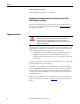
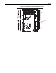

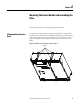
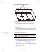
Table Of Contents
- Front Cover
- Important User Information
- Summary of Changes
- Table of Contents
- Introduction
- About the Drive
- Identifying the Drive by Cabinet Assembly ID Number
- LiquiFlo 2.0 Drive Component Locations
- Identifying the Power Module by Model Number
- AC Line I/O Board Description (Frame 3 Only)
- Standard I/O Board Description (Frame 3 Only)
- Combined I/O Board Description (Frame 4 Only)
- DPI Communication Ports
- Optional Equipment
- Planning the Installation
- Mounting The Power Module and Grounding the Drive
- Installing Input and Output Power Wiring
- Completing the Installation
- Using the Start-up Routines
- Programming Basics
- Parameter Descriptions
- Troubleshooting the Drive
- Verify that the DC Bus Capacitors are Discharged Before Servicing the Drive
- Determining Drive Status Using the Status LEDs
- About Alarms
- About Faults
- Diagnostic Parameters
- Common Symptoms and Corrective Actions
- Replacement Parts
- Board Replacement, Firmware Setup Procedures
- Troubleshooting the Drive Using the OIM
- Checking the Power Modules with Input Power Off
- Technical Specifications
- Using the OIM
- Installing and Removing the OIM
- Display Description
- OIM Menu Structure
- Powering Up and Adjusting the OIM
- Selecting a Device in the System
- Using the OIM to Program the Drive
- Monitoring the Drive Using the Process Display Screen on the OIM
- Displaying and Changing the OIM Reference
- Customizing the Process Display Screen
- Customizing the Function Keys
- Controlling the Drive From the OIM
- LiquiFlo 2.0 Drive Frame 3 Wiring Diagrams
- LiquiFlo 2.0 Drive Frame 4 Wiring Diagrams
- Index
- Back Cover

48 Rockwell Automation Publication D2-3518-3 - May 2013
Chapter 4
Use the following procedure to lift and mount the LiquiFlo 2.0 power module:
1. Use an overhead or portable hoist (minimum 2 ton rated capacity) to
attach a free-fall chain to the chain secured to the power module. Take up
any vertical slack in the chain.
2. Use the hoist to carefully lift the power module from the horizontal
shipping pallet.
3. Position the power module in the prepared mounting location.
4. Machine fasten the power module enclosure using 1/2-inch bolts, grade 5
or better, with compression washers. Recommended tightening torque is
11.3...13.5 N•m (100...120 lb•in).
ATTENTION: Do not use input and output busbars for lifting or handling.
Otherwise, damage to equipment may result.
ATTENTION: Mechanically support conductors to minimize mechanical load on
input and output busbars. Otherwise, damage to equipment may result.