
Owner's manual
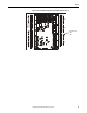

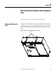
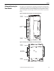
Table Of Contents
- Front Cover
- Important User Information
- Summary of Changes
- Table of Contents
- Introduction
- About the Drive
- Identifying the Drive by Cabinet Assembly ID Number
- LiquiFlo 2.0 Drive Component Locations
- Identifying the Power Module by Model Number
- AC Line I/O Board Description (Frame 3 Only)
- Standard I/O Board Description (Frame 3 Only)
- Combined I/O Board Description (Frame 4 Only)
- DPI Communication Ports
- Optional Equipment
- Planning the Installation
- Mounting The Power Module and Grounding the Drive
- Installing Input and Output Power Wiring
- Completing the Installation
- Using the Start-up Routines
- Programming Basics
- Parameter Descriptions
- Troubleshooting the Drive
- Verify that the DC Bus Capacitors are Discharged Before Servicing the Drive
- Determining Drive Status Using the Status LEDs
- About Alarms
- About Faults
- Diagnostic Parameters
- Common Symptoms and Corrective Actions
- Replacement Parts
- Board Replacement, Firmware Setup Procedures
- Troubleshooting the Drive Using the OIM
- Checking the Power Modules with Input Power Off
- Technical Specifications
- Using the OIM
- Installing and Removing the OIM
- Display Description
- OIM Menu Structure
- Powering Up and Adjusting the OIM
- Selecting a Device in the System
- Using the OIM to Program the Drive
- Monitoring the Drive Using the Process Display Screen on the OIM
- Displaying and Changing the OIM Reference
- Customizing the Process Display Screen
- Customizing the Function Keys
- Controlling the Drive From the OIM
- LiquiFlo 2.0 Drive Frame 3 Wiring Diagrams
- LiquiFlo 2.0 Drive Frame 4 Wiring Diagrams
- Index
- Back Cover
Rockwell Automation Publication D2-3518-3 - May 2013 43
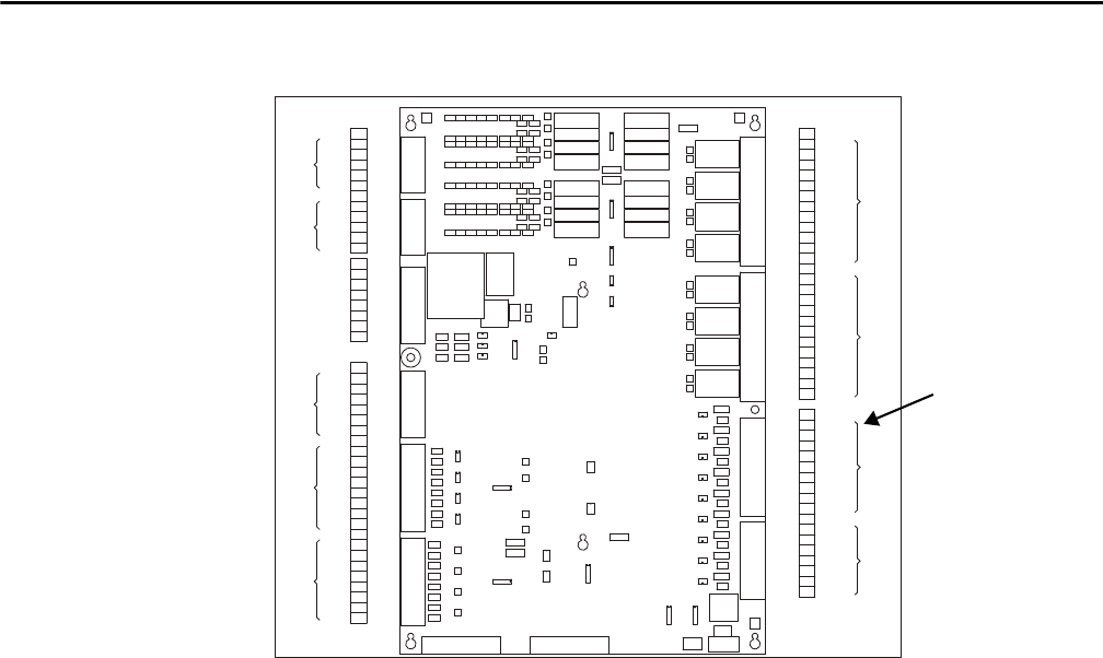
Chapter 3
Figure 18 - Frame 4 Combined I/O (partial view) with Gate Kill Connections
5
1
2
3
4
5
1
7
6
TB4
3
2
4
7
6
8
9
TB3
1
2
6
3
4
5
6
7
8
9
10
2
11
12
TB2
1
4
3
5
10
8
7
9
12
11
TB1
DI 6
DI 24V-
DI COM 2
DI 8
DI 7
DI 2
DI 24V-
DI 24V+
DI 5
DI 4
DI COM 1
DI 3
DI 24V+
DI 1
GATEKILL -
GATEKILL +
DIGITAL
OUTPUT
2
DO 8 NO
DO 8 COM
DO 3 NC
DO 8 NC
DO 7 NO
DO 7 COM
DO 7 NC
DO 6 NO
DO 6 COM
DO 6 NC
DO 5 NO
DIGITAL
OUTPUT
1
DO 4 COM
DO 5 COM
DO 5 NC
DO 4 NO
DO 3 NO
DO 4 NC
DO 3 COM
DO 1 NO
DO 2 COM
DO 2 NO
DO 2 NC
DO 1 NC
DO 1 COM
DIGITAL
INPUT
2
DIGITAL
INPUT
1
+12V 1
AO 1-
OUTPUT
ANALOG
AO 3- 6
AO 4- 8
AO 4+ 7
AO 2-
AO 3+ 5
4
AO 2+ 3
2
INPUT
ANALOG
ENCODER
INPUT
TB9
AO 1+ 1
AI 4-
AI 4+
8
7
AI 3-
AI 3+
6
5
AI 2-
AI 2+
4
3
B+
TB8
AI 1+
AI 1- 2
1
B- 6
A+ 3
A-
5
4
COMMON
2
G1 1
TEMPSW RCT
TEMPSW INV
VOLTAGE
GRID
SHUNT TRIP 3
PRECHARGE FB 7
TB10
5
6
SW 24V 4
G3 5
TB7
CNTRL PWR
PRECHARGE OUT 2
1
G2 3
VOLTAGE
LINE
L2 3
TB6
L3 5
TB5
L1 1
Gate Kill Connections
TB3-8
TB3-9