
Owner's manual
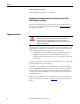
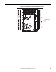

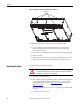
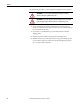
Table Of Contents
- Front Cover
- Important User Information
- Summary of Changes
- Table of Contents
- Introduction
- About the Drive
- Identifying the Drive by Cabinet Assembly ID Number
- LiquiFlo 2.0 Drive Component Locations
- Identifying the Power Module by Model Number
- AC Line I/O Board Description (Frame 3 Only)
- Standard I/O Board Description (Frame 3 Only)
- Combined I/O Board Description (Frame 4 Only)
- DPI Communication Ports
- Optional Equipment
- Planning the Installation
- Mounting The Power Module and Grounding the Drive
- Installing Input and Output Power Wiring
- Completing the Installation
- Using the Start-up Routines
- Programming Basics
- Parameter Descriptions
- Troubleshooting the Drive
- Verify that the DC Bus Capacitors are Discharged Before Servicing the Drive
- Determining Drive Status Using the Status LEDs
- About Alarms
- About Faults
- Diagnostic Parameters
- Common Symptoms and Corrective Actions
- Replacement Parts
- Board Replacement, Firmware Setup Procedures
- Troubleshooting the Drive Using the OIM
- Checking the Power Modules with Input Power Off
- Technical Specifications
- Using the OIM
- Installing and Removing the OIM
- Display Description
- OIM Menu Structure
- Powering Up and Adjusting the OIM
- Selecting a Device in the System
- Using the OIM to Program the Drive
- Monitoring the Drive Using the Process Display Screen on the OIM
- Displaying and Changing the OIM Reference
- Customizing the Process Display Screen
- Customizing the Function Keys
- Controlling the Drive From the OIM
- LiquiFlo 2.0 Drive Frame 3 Wiring Diagrams
- LiquiFlo 2.0 Drive Frame 4 Wiring Diagrams
- Index
- Back Cover
42 Rockwell Automation Publication D2-3518-3 - May 2013
Chapter 3
Recommended Motor Lead Lengths
Motor lead lengths can total up to 76 m (250 ft).
Verifying Power Module Output Current Rating Is Greater Than
Chiller Running Load Amps
Verify that the LiquiFlo 2.0 power module output current rating is equal to or
greater than the running load amps (RLA) of the chiller. Table 2 on page 24
lists
the output current values.
Stopping the Drive
Depending on the requirements of the application, the LiquiFlo 2.0 drive can be
programmed to provide either a coast-to-rest or a ramp-to-rest operational stop
without physical separation of the power source from the motor.
• A coast-to-rest stop turns off the gate drive to the IGBT power devices.
• A ramp-to-rest stop continues to fire the IGBT power devices in a
controlled manner until the motor comes to a stop, and then turns off the
power devices.
You can also program zero speed with power maintained to the motor, but in this
condition, the drive is not actually stopped.
In addition to the operational stop, the LiquiFlo 2.0 power module provides a
hardwired gate kill. This function provides a two-wire emergency stop circuit
that does not depend on software or on the transmission of commands over a
communications network. When the two-wire circuit is opened, the gate drive to
the IGBTs is removed.
In Frame 3, the gate kill function is provided by a two-position terminal block
(A33) located on the power module. See Figure 18
for gate kill connections in
Frame 4.
ATTENTION: You must provide an external, hardwired emergency stop circuit
outside of the drive circuitry. This circuit must disable the system in case of
improper operation. Uncontrolled machine operation may result if this
emergency stop circuit is not implemented. Failure to observe this precaution
could result in bodily injury.