
Owner's manual
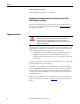

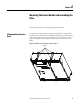
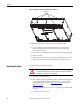
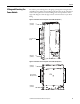
Table Of Contents
- Front Cover
- Important User Information
- Summary of Changes
- Table of Contents
- Introduction
- About the Drive
- Identifying the Drive by Cabinet Assembly ID Number
- LiquiFlo 2.0 Drive Component Locations
- Identifying the Power Module by Model Number
- AC Line I/O Board Description (Frame 3 Only)
- Standard I/O Board Description (Frame 3 Only)
- Combined I/O Board Description (Frame 4 Only)
- DPI Communication Ports
- Optional Equipment
- Planning the Installation
- Mounting The Power Module and Grounding the Drive
- Installing Input and Output Power Wiring
- Completing the Installation
- Using the Start-up Routines
- Programming Basics
- Parameter Descriptions
- Troubleshooting the Drive
- Verify that the DC Bus Capacitors are Discharged Before Servicing the Drive
- Determining Drive Status Using the Status LEDs
- About Alarms
- About Faults
- Diagnostic Parameters
- Common Symptoms and Corrective Actions
- Replacement Parts
- Board Replacement, Firmware Setup Procedures
- Troubleshooting the Drive Using the OIM
- Checking the Power Modules with Input Power Off
- Technical Specifications
- Using the OIM
- Installing and Removing the OIM
- Display Description
- OIM Menu Structure
- Powering Up and Adjusting the OIM
- Selecting a Device in the System
- Using the OIM to Program the Drive
- Monitoring the Drive Using the Process Display Screen on the OIM
- Displaying and Changing the OIM Reference
- Customizing the Process Display Screen
- Customizing the Function Keys
- Controlling the Drive From the OIM
- LiquiFlo 2.0 Drive Frame 3 Wiring Diagrams
- LiquiFlo 2.0 Drive Frame 4 Wiring Diagrams
- Index
- Back Cover

Rockwell Automation Publication D2-3518-3 - May 2013 41
Chapter 3
Verifying the Site Provides for Recommended Air Flow Clearances
Be sure there is adequate clearance for air circulation around the enclosure. A
6-inch minimum clearance is required wherever vents are located in the cabinet.
Verifying Power Module Input Ratings Match Supplied Power
Verify that plant power meets the input power requirements of the power module
circuitry for the LiquiFlo 2.0 drive. See Tab le 2 o n p a g e 24
for input power rating
specifications. Be sure input power to the power module corresponds to the
nameplate voltage, current, and frequency of the power module.
Wiring Requirements for the
Drive
Evaluate the input power wire sizes, branch circuit protection, and control wiring
before continuing with the drive installation (Chapter 6
).
Determining Wire Size Requirements
Determine wire size based on current requirements, size of conduit openings, and
applicable local, national, and international codes (for example, NEC/CEC
regulations).
Conduit Entry Opening Sizes
Determine the size of the conduit openings in the cabinet that the drive is
mounted in so that the wire planned for a specific entry point will fit through the
opening.
Recommended Power Wire Sizes
Use copper input power wiring that is sized according to applicable codes to
handle the continuous-rated input current of the drive. Use copper output wiring
that is sized according to applicable codes to handle the continuous-rated output
current of the drive.
Recommended Control and Signal Wire Sizes
The recommended wire size to connect I/O signals to the control terminal block
is 4 mm
2
(12 AWG). Recommended terminal tightening torque is 0.8...1 N•m
(7...9 lb•in).
ATTENTION: You are responsible for conforming with all applicable local,
national, and international codes. Failure to observe this precaution could result
in damage to, or destruction of, the equipment.