
Owner's manual
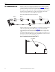
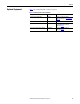

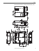
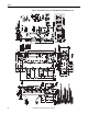
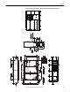
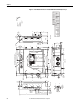
Table Of Contents
- Front Cover
- Important User Information
- Summary of Changes
- Table of Contents
- Introduction
- About the Drive
- Identifying the Drive by Cabinet Assembly ID Number
- LiquiFlo 2.0 Drive Component Locations
- Identifying the Power Module by Model Number
- AC Line I/O Board Description (Frame 3 Only)
- Standard I/O Board Description (Frame 3 Only)
- Combined I/O Board Description (Frame 4 Only)
- DPI Communication Ports
- Optional Equipment
- Planning the Installation
- Mounting The Power Module and Grounding the Drive
- Installing Input and Output Power Wiring
- Completing the Installation
- Using the Start-up Routines
- Programming Basics
- Parameter Descriptions
- Troubleshooting the Drive
- Verify that the DC Bus Capacitors are Discharged Before Servicing the Drive
- Determining Drive Status Using the Status LEDs
- About Alarms
- About Faults
- Diagnostic Parameters
- Common Symptoms and Corrective Actions
- Replacement Parts
- Board Replacement, Firmware Setup Procedures
- Troubleshooting the Drive Using the OIM
- Checking the Power Modules with Input Power Off
- Technical Specifications
- Using the OIM
- Installing and Removing the OIM
- Display Description
- OIM Menu Structure
- Powering Up and Adjusting the OIM
- Selecting a Device in the System
- Using the OIM to Program the Drive
- Monitoring the Drive Using the Process Display Screen on the OIM
- Displaying and Changing the OIM Reference
- Customizing the Process Display Screen
- Customizing the Function Keys
- Controlling the Drive From the OIM
- LiquiFlo 2.0 Drive Frame 3 Wiring Diagrams
- LiquiFlo 2.0 Drive Frame 4 Wiring Diagrams
- Index
- Back Cover

36 Rockwell Automation Publication D2-3518-3 - May 2013
Chapter 3
Table 4 - Environmental Conditions
Determining Total Area Required Based on Drive Dimensions
Overall drive dimensions are identified in these figures:
• Frame 3 drives 180264-A03 and 180264-A06 in Figure 14
• Frame 4 drives 180580-A07 and 180580-A09 in Figure 16
Overall power module dimensions are identified in these figures:
• Frame 3 power modules LF200460AAR and LF200608CCR in Figure 15
• Frame 4 power modules LF200900CCRand LF201215CCR in Figure 17
Condition Specification
Operating Temperature
(inside NEMA/UL Type 1 enclosure)
0...+55 °C
(1)
(32...131 °F)
(1) With typical heat rise inside a cabinet, 40 ° C (104 °F) ambient outside usually results in 55 ° C (131 °F) inside.
Ambient Temperature
(outside NEMA/UL Type 1 enclosure)
0...+40 °C (32...104 ° F)
Storage Temperature (Ambient) - 40...65 °C (- 40...149 °F)
Humidity 5%...95% (non-condensing)