
Owner's manual
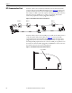

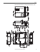
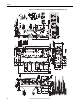
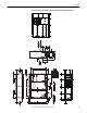
Table Of Contents
- Front Cover
- Important User Information
- Summary of Changes
- Table of Contents
- Introduction
- About the Drive
- Identifying the Drive by Cabinet Assembly ID Number
- LiquiFlo 2.0 Drive Component Locations
- Identifying the Power Module by Model Number
- AC Line I/O Board Description (Frame 3 Only)
- Standard I/O Board Description (Frame 3 Only)
- Combined I/O Board Description (Frame 4 Only)
- DPI Communication Ports
- Optional Equipment
- Planning the Installation
- Mounting The Power Module and Grounding the Drive
- Installing Input and Output Power Wiring
- Completing the Installation
- Using the Start-up Routines
- Programming Basics
- Parameter Descriptions
- Troubleshooting the Drive
- Verify that the DC Bus Capacitors are Discharged Before Servicing the Drive
- Determining Drive Status Using the Status LEDs
- About Alarms
- About Faults
- Diagnostic Parameters
- Common Symptoms and Corrective Actions
- Replacement Parts
- Board Replacement, Firmware Setup Procedures
- Troubleshooting the Drive Using the OIM
- Checking the Power Modules with Input Power Off
- Technical Specifications
- Using the OIM
- Installing and Removing the OIM
- Display Description
- OIM Menu Structure
- Powering Up and Adjusting the OIM
- Selecting a Device in the System
- Using the OIM to Program the Drive
- Monitoring the Drive Using the Process Display Screen on the OIM
- Displaying and Changing the OIM Reference
- Customizing the Process Display Screen
- Customizing the Function Keys
- Controlling the Drive From the OIM
- LiquiFlo 2.0 Drive Frame 3 Wiring Diagrams
- LiquiFlo 2.0 Drive Frame 4 Wiring Diagrams
- Index
- Back Cover
Rockwell Automation Publication D2-3518-3 - May 2013 35
Chapter 3
Planning the Installation
This chapter provides information for planning a LiquiFlo 2.0 drive installation.
General Requirements for
the Installation Site
Always properly plan the installation before installing a LiquiFlo 2.0 drive to be
sure that the environment and operating conditions are satisfactory. Read the
following recommendations before continuing with drive installation.
Making Sure Environmental Conditions are Met
Before deciding on an installation site, consider the following guidelines:
• Verify that NEMA/UL Type 1 enclosure drives can be kept clean and dry.
• Verify that the area chosen allows for proper airflow. See Verif ying the Site
Provides for Recommended Air Flow Clearances on page 41.
• Be sure that the NEMA/UL Type 1 enclosure is installed away from oil,
coolants, and other airborne contaminants.
• Do not install the drive above 1000 m (3300 ft) without derating output
power. For every 91.4 m (300 ft) above 1000 m (3300 ft), derate the
output current 1%.
• Verify that the drive location meets the environmental conditions specified
in Ta bl e 4
.
• Floor-mounted units should be attached to the floor with the C-channel
rails provided. See Figure 14
and Figure 16.
ATTENTION: Only qualified electrical personnel familiar with the construction
and operation of this equipment and the hazards involved should install, adjust,
operate, or service this equipment. Read and understand this manual and other
applicable manuals in their entirety before proceeding. Failure to observe this
precaution could result in severe bodily injury or loss of life.
ATTENTION: Use of power factor correction capacitors on the output of the
drive can result in erratic operation of the motor, nuisance tripping, and/or
permanent damage to the drive. Remove power factor correction capacitors
before proceeding. Failure to observe this precaution could result in damage to,
or destruction of, the equipment.
ATTENTION: You are responsible for conforming with all applicable local,
national, and international codes. Failure to observe this precaution could result
in damage to, or destruction of, the equipment.