
Owner's manual
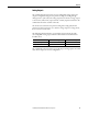
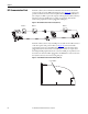


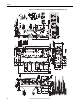

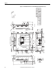
Table Of Contents
- Front Cover
- Important User Information
- Summary of Changes
- Table of Contents
- Introduction
- About the Drive
- Identifying the Drive by Cabinet Assembly ID Number
- LiquiFlo 2.0 Drive Component Locations
- Identifying the Power Module by Model Number
- AC Line I/O Board Description (Frame 3 Only)
- Standard I/O Board Description (Frame 3 Only)
- Combined I/O Board Description (Frame 4 Only)
- DPI Communication Ports
- Optional Equipment
- Planning the Installation
- Mounting The Power Module and Grounding the Drive
- Installing Input and Output Power Wiring
- Completing the Installation
- Using the Start-up Routines
- Programming Basics
- Parameter Descriptions
- Troubleshooting the Drive
- Verify that the DC Bus Capacitors are Discharged Before Servicing the Drive
- Determining Drive Status Using the Status LEDs
- About Alarms
- About Faults
- Diagnostic Parameters
- Common Symptoms and Corrective Actions
- Replacement Parts
- Board Replacement, Firmware Setup Procedures
- Troubleshooting the Drive Using the OIM
- Checking the Power Modules with Input Power Off
- Technical Specifications
- Using the OIM
- Installing and Removing the OIM
- Display Description
- OIM Menu Structure
- Powering Up and Adjusting the OIM
- Selecting a Device in the System
- Using the OIM to Program the Drive
- Monitoring the Drive Using the Process Display Screen on the OIM
- Displaying and Changing the OIM Reference
- Customizing the Process Display Screen
- Customizing the Function Keys
- Controlling the Drive From the OIM
- LiquiFlo 2.0 Drive Frame 3 Wiring Diagrams
- LiquiFlo 2.0 Drive Frame 4 Wiring Diagrams
- Index
- Back Cover
32 Rockwell Automation Publication D2-3518-3 - May 2013
Chapter 2
DPI Communication Ports
For Frame 3 drives, the Communication Interface board contains three DIN
connectors that are used as DPI communication ports (Figure 12
). These ports
provide communication between the LiquiFlo 2.0 drive and other DPI devices
(for example, an OIM or a personal computer running the VS Utilities software).
The three connectors (DPI ports 3, 4, and 5) are equivalent. This manual
assumes that peripherals are always plugged into DPI port 3.
Figure 12 - DPI Communication Interface Board (Frame 3)
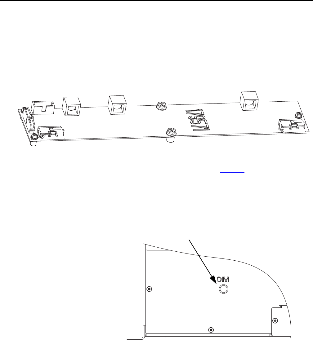
For Frame 4 drives, there is only one DPI port, accessible via the OIM connector
on the front panel of the power module (see Figure 13
). An internal cable
connects this connector to the DIN connector on the control board. A device
plugged directly into this connector uses DPI port 3. If there is a requirement
that multiple DPI peripheral devices be connected, a DPI port expander box can
be used, but no device should be plugged into the DPI Port 2 connector because
the rectifier connects to the inverter using that port.
Figure 13 - Power Module Bottom Left Front View (Frame 4)
DPI Port 5 DPI Port 4 DPI Port 3
Connect OIM Here