
Owner's manual
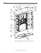
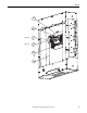
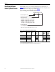
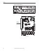
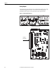
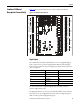
Table Of Contents
- Front Cover
- Important User Information
- Summary of Changes
- Table of Contents
- Introduction
- About the Drive
- Identifying the Drive by Cabinet Assembly ID Number
- LiquiFlo 2.0 Drive Component Locations
- Identifying the Power Module by Model Number
- AC Line I/O Board Description (Frame 3 Only)
- Standard I/O Board Description (Frame 3 Only)
- Combined I/O Board Description (Frame 4 Only)
- DPI Communication Ports
- Optional Equipment
- Planning the Installation
- Mounting The Power Module and Grounding the Drive
- Installing Input and Output Power Wiring
- Completing the Installation
- Using the Start-up Routines
- Programming Basics
- Parameter Descriptions
- Troubleshooting the Drive
- Verify that the DC Bus Capacitors are Discharged Before Servicing the Drive
- Determining Drive Status Using the Status LEDs
- About Alarms
- About Faults
- Diagnostic Parameters
- Common Symptoms and Corrective Actions
- Replacement Parts
- Board Replacement, Firmware Setup Procedures
- Troubleshooting the Drive Using the OIM
- Checking the Power Modules with Input Power Off
- Technical Specifications
- Using the OIM
- Installing and Removing the OIM
- Display Description
- OIM Menu Structure
- Powering Up and Adjusting the OIM
- Selecting a Device in the System
- Using the OIM to Program the Drive
- Monitoring the Drive Using the Process Display Screen on the OIM
- Displaying and Changing the OIM Reference
- Customizing the Process Display Screen
- Customizing the Function Keys
- Controlling the Drive From the OIM
- LiquiFlo 2.0 Drive Frame 3 Wiring Diagrams
- LiquiFlo 2.0 Drive Frame 4 Wiring Diagrams
- Index
- Back Cover
28 Rockwell Automation Publication D2-3518-3 - May 2013
Chapter 2
Analog Outputs
The single analog output channel can be configured using Analog Out Config
(340) and Analog Out1 Sel (342) to select any one of 31 analog outputs.
Terminals 8 and 9 output 4...20 mA. Terminals 6 and 7 output 0...10 V.
Figure 10 - Standard I/O Board (Frame 3)
+
+
+
+
+
+
+
+
+
+
+
11
+
1
2
24 VOLT AC/DC
24 VOLT AC/DC
C78
C79 C80 C81 C82 C83
C77
R83
R77
A
2
A3
R81
R75
C75
R82
R76
R84
R78
R85
R79
R86
R80
U24
R74
C71
U8
A
4
Q3
U27 U28 U29
Q2
J3
A
1
Standard I/O Terminal Block (Detail)
Standard I/O Board
Standard I/O
Terminal Block