
Owner's manual
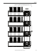

Table Of Contents
- Front Cover
- Important User Information
- Summary of Changes
- Table of Contents
- Introduction
- About the Drive
- Identifying the Drive by Cabinet Assembly ID Number
- LiquiFlo 2.0 Drive Component Locations
- Identifying the Power Module by Model Number
- AC Line I/O Board Description (Frame 3 Only)
- Standard I/O Board Description (Frame 3 Only)
- Combined I/O Board Description (Frame 4 Only)
- DPI Communication Ports
- Optional Equipment
- Planning the Installation
- Mounting The Power Module and Grounding the Drive
- Installing Input and Output Power Wiring
- Completing the Installation
- Using the Start-up Routines
- Programming Basics
- Parameter Descriptions
- Troubleshooting the Drive
- Verify that the DC Bus Capacitors are Discharged Before Servicing the Drive
- Determining Drive Status Using the Status LEDs
- About Alarms
- About Faults
- Diagnostic Parameters
- Common Symptoms and Corrective Actions
- Replacement Parts
- Board Replacement, Firmware Setup Procedures
- Troubleshooting the Drive Using the OIM
- Checking the Power Modules with Input Power Off
- Technical Specifications
- Using the OIM
- Installing and Removing the OIM
- Display Description
- OIM Menu Structure
- Powering Up and Adjusting the OIM
- Selecting a Device in the System
- Using the OIM to Program the Drive
- Monitoring the Drive Using the Process Display Screen on the OIM
- Displaying and Changing the OIM Reference
- Customizing the Process Display Screen
- Customizing the Function Keys
- Controlling the Drive From the OIM
- LiquiFlo 2.0 Drive Frame 3 Wiring Diagrams
- LiquiFlo 2.0 Drive Frame 4 Wiring Diagrams
- Index
- Back Cover

Rockwell Automation Publication D2-3518-3 - May 2013 269
Index
programming basics 51
proportional control
93
R
ramp-to-rest 38
ratings
enclosure
20
input current 20
input power
20
input voltage
20
output current 20
rectifier sequencing
72
refrigerant
230
replacement parts
frame 3 drive
214
frame 3 power module
215
frame 4 drive
216
frame 4 power module
217
ordering
217
RLA 38
runnning load amps
38
S
sequencing, rectifier 72
signal loss
Analog In 1
139
Analog In 2
141
signal wire sizes 37
site requirements
31
starting the drive using the OIM
242
start-up routines
accessing
50
exiting
50
preparing for
49
running 50
start-up menu
50
status info submenu
223
status LED definitions
hardware failure
194
inverter
194
rectifier
194
status LEDs
192
location (frame 3)
193
location (frame 4)
193
stopping the drive
coast-to-rest
38
emergency stop circuit
5
gate kill
38
ramp-to-rest 38
using the OIM
242
storage temperature
32, 229
T
technical specifications
cooling system specifications
230
environmental conditions
229
service conditions
229
technical support
7, 227
temperature
ambient
32
operating
inside NEMA/UL Type 1 enclosure
32,
229
outside NEMA/UL Type 1 enclosure
32,
229
storage
32, 229
time stamp, fault queue
198
troubleshooting
191
common symptoms, corrective actions
212
drive does not
respond to speed command
213
reverse motor direction
213
start from start, run, or jog inputs wired
to the terminal block
212
start or jog from OIM
212
motor and/or drive does not accelerate to
commanded speed
213
motor operation is unstable
213
stopping the drive results in a decel inhibit
fault
213
using the OIM
222
type 2 alarms 154
U
user sets
loading and saving using the OIM
238
V
version
how to determine
223
version levels
component
224
OIM component
225
OIM product 225
product
224
VS Utilities
7, 28, 29, 49, 58, 198, 199, 204
W
wire sizes
control and signal
37
motor lead lengths
38
power
37
wiring
input power
45
output power
46
requirements, drive
37
wiring diagrams
frame 3
cabinet wiring
244
power module (sheet 1)
245
power module (sheet 2)
246
power module IGBT (sheet 5)
249
power module inverter (sheet 4)
248
power module rectifier (sheet 3)
247
frame 4
cabinet wiring
252
power module (sheet1)
253
power module control (sheet 2)
254