
Owner's manual
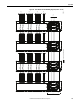

Table Of Contents
- Front Cover
- Important User Information
- Summary of Changes
- Table of Contents
- Introduction
- About the Drive
- Identifying the Drive by Cabinet Assembly ID Number
- LiquiFlo 2.0 Drive Component Locations
- Identifying the Power Module by Model Number
- AC Line I/O Board Description (Frame 3 Only)
- Standard I/O Board Description (Frame 3 Only)
- Combined I/O Board Description (Frame 4 Only)
- DPI Communication Ports
- Optional Equipment
- Planning the Installation
- Mounting The Power Module and Grounding the Drive
- Installing Input and Output Power Wiring
- Completing the Installation
- Using the Start-up Routines
- Programming Basics
- Parameter Descriptions
- Troubleshooting the Drive
- Verify that the DC Bus Capacitors are Discharged Before Servicing the Drive
- Determining Drive Status Using the Status LEDs
- About Alarms
- About Faults
- Diagnostic Parameters
- Common Symptoms and Corrective Actions
- Replacement Parts
- Board Replacement, Firmware Setup Procedures
- Troubleshooting the Drive Using the OIM
- Checking the Power Modules with Input Power Off
- Technical Specifications
- Using the OIM
- Installing and Removing the OIM
- Display Description
- OIM Menu Structure
- Powering Up and Adjusting the OIM
- Selecting a Device in the System
- Using the OIM to Program the Drive
- Monitoring the Drive Using the Process Display Screen on the OIM
- Displaying and Changing the OIM Reference
- Customizing the Process Display Screen
- Customizing the Function Keys
- Controlling the Drive From the OIM
- LiquiFlo 2.0 Drive Frame 3 Wiring Diagrams
- LiquiFlo 2.0 Drive Frame 4 Wiring Diagrams
- Index
- Back Cover

Rockwell Automation Publication D2-3518-3 - May 2013 265
Index
M
model numbers 20
motor lead lengths
38
motor type
induction
75
reluctance
75
synchronous permanent magnet
75
mounting
drive
41
power module
43
N
nameplate
drive
9
power module
20
O
OIM
cables
231
controlling the drive from
242
customizing the function keys
239
customizing the process display screen 239
display description
233
display timeout period, setting
242
drive status parameters, accessing 223
fast power up
236
fault parameters, accessing
223
fault queue, accessing 222
installing and removing
231
key descriptions
234
loading and saving user sets 238
menu structure
235
monitoring the drive
238
parameters, accessing 58
parameters, viewing and adjusting
237
powering up and adjusting the OIM
236
process display screen 238
product version, how to determine
223
program protection, selecting
62
reference, displaying and changing
239
removing while the drive is powered
233
resetting the display
236
reverse video, selecting
242
screen contrast, adjusting
236
selecting a device
236
starting the drive
242
stopping the drive
242
using
231
using to program the drive
236
version information
224
viewing and adjusting parameters
237
viewing component version level
224
viewing OIM component version level 225
viewing OIM product version level
225
viewing product version level
224
viewing the inverter from
224
viewing the rectifier from
224
operating temperature
229
optional equipment
29
optional standard I/O board description
(frame 3 only)
23
output current rating
20, 38
output IGBT components
226
output power, derating
31
outputs
analog
AC line I/O board
21
combined I/O board
27
optional standard I/O board
24
digital
AC line I/O board
21
combined I/O board
26
optional standard I/O board
23
overvoltage faults 104
P
P0 LiquiFlo 2.0 224
P2 Active Rectifier
224
parameter types
bit
51
configurable
51
numbered list 51
numeric
51
read-only
51
tunable 51
parameters
access level, selecting
59
accessing
58
using the OIM 58
using VS Utilities
58
advanced
59
basic 59
basic access level
inverter
60
rectifier 60
descriptions
65
diagnostic
211
drive status parameters 223
inverter
66
inverter view
53
organization
52
organized by file and group
inverter
53
rectifier
56
passwords and security
62
rectifier
158
rectifier view
56
symbols
65
viewing
58
viewing and adjusting using the OIM
237
Parameters, inverter
Accel Time 1 (140)
99
Accel Time 2 (141)
99
Alarm 1 @ Fault (229)
123
Alarm 2 @ Fault (230) 123
Alarm Config 1 (259)
127
Analog In 1 Hi (322)
138
Analog In 1 Lo (323)
139
Analog In 1 Loss (324)
139
Analog In 2 Hi (325)
140
Analog In 2 Lo (326)
140
Analog In 2 Loss (327)
141
Analog In1 Value (16)
68
Analog In2 Value (17)
68