
Owner's manual
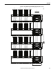


Table Of Contents
- Front Cover
- Important User Information
- Summary of Changes
- Table of Contents
- Introduction
- About the Drive
- Identifying the Drive by Cabinet Assembly ID Number
- LiquiFlo 2.0 Drive Component Locations
- Identifying the Power Module by Model Number
- AC Line I/O Board Description (Frame 3 Only)
- Standard I/O Board Description (Frame 3 Only)
- Combined I/O Board Description (Frame 4 Only)
- DPI Communication Ports
- Optional Equipment
- Planning the Installation
- Mounting The Power Module and Grounding the Drive
- Installing Input and Output Power Wiring
- Completing the Installation
- Using the Start-up Routines
- Programming Basics
- Parameter Descriptions
- Troubleshooting the Drive
- Verify that the DC Bus Capacitors are Discharged Before Servicing the Drive
- Determining Drive Status Using the Status LEDs
- About Alarms
- About Faults
- Diagnostic Parameters
- Common Symptoms and Corrective Actions
- Replacement Parts
- Board Replacement, Firmware Setup Procedures
- Troubleshooting the Drive Using the OIM
- Checking the Power Modules with Input Power Off
- Technical Specifications
- Using the OIM
- Installing and Removing the OIM
- Display Description
- OIM Menu Structure
- Powering Up and Adjusting the OIM
- Selecting a Device in the System
- Using the OIM to Program the Drive
- Monitoring the Drive Using the Process Display Screen on the OIM
- Displaying and Changing the OIM Reference
- Customizing the Process Display Screen
- Customizing the Function Keys
- Controlling the Drive From the OIM
- LiquiFlo 2.0 Drive Frame 3 Wiring Diagrams
- LiquiFlo 2.0 Drive Frame 4 Wiring Diagrams
- Index
- Back Cover

264 Rockwell Automation Publication D2-3518-3 - May 2013
Index
descriptions and corrective actions
frame 3
199
frame 4 204
fault parameters, accessing using the OIM
223
fault queue
198
IOC 186
names cross-referenced by fault number
210
time stamp
198
firmware
setup procedures, after board replacement
frame 3
218
frame 4
220
firmware setup, after board replacement
frame 3
I/O board (AC line I/O board or standard
I/O board)
220
inverter control board 218
inverter power interface board
219
rectifier control board
219
rectifier power interface board
220
frame 4
combined control board
220
combined power board 221
firmware versions
frame 3
inverter
6
rectifier 6
frame 4
inverter
6
rectifier 6
how to determine
224
function keys
customizing
239
fuses
frame 3
class CC, 600 V, 1 A
10
class CC, 600 V, 20 A
10
class CC, 600 V, 25 A 10
class CC, 600 V, 5 A
10
class RK5, 600 V, 15 A
10
frame 4
Class CC, 600V, 1 A
15
Class CC, 600V, 10 A
15
Class CC, 600V, 20 A
15
Class CC, 600V, 25 A
15
Class RK-5, 600V, 10 A
15
Class T, 600V, 300 A
15
G
gate kill 38
H
hardware version, how to determine 223
humidity
32
I
I/O board description
AC line I/O board (frame 3 only)
21
combined I/O board (frame 4 only)
25
optional standard I/O board (frame 3 only)
23
IGBT, output components
226
input
ratings
37
input current rating
20
input diode components
226
input power, drive
20
inputs
analog
AC line I/O board
21
combined I/O board
26
optional standard I/O board
23
digital
AC line I/O board
21
combined I/O board
25
optional standard I/O board 23
installation
checklist
47
environmental conditions
31
planning
31
site requirements
31
total area required
32
instantaneous overcurrent (IOC) fault 186
integral control
93
inverter/rectifier communication
136
IOC fault
186
J
jog
forward input, drive response
151
reverse input, drive response
151
K
key descriptions, OIM 234
kits
OIM door-mount bezel kit
29
OIM LCD hand-held cable
29
operator interface module (OIM)
29
serial converter with VS Utilities software
29
L
LED status definitions
hardware failure
194
inverter
194
rectifier
194
LEDs
location (frame 3)
193
location (frame 4)
193
status
192
lift point locations
frame 3
drive
41
power module
43
frame 4
drive
42
power module
43
lifting
drive
41
power module
43