
Owner's manual
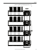


Table Of Contents
- Front Cover
- Important User Information
- Summary of Changes
- Table of Contents
- Introduction
- About the Drive
- Identifying the Drive by Cabinet Assembly ID Number
- LiquiFlo 2.0 Drive Component Locations
- Identifying the Power Module by Model Number
- AC Line I/O Board Description (Frame 3 Only)
- Standard I/O Board Description (Frame 3 Only)
- Combined I/O Board Description (Frame 4 Only)
- DPI Communication Ports
- Optional Equipment
- Planning the Installation
- Mounting The Power Module and Grounding the Drive
- Installing Input and Output Power Wiring
- Completing the Installation
- Using the Start-up Routines
- Programming Basics
- Parameter Descriptions
- Troubleshooting the Drive
- Verify that the DC Bus Capacitors are Discharged Before Servicing the Drive
- Determining Drive Status Using the Status LEDs
- About Alarms
- About Faults
- Diagnostic Parameters
- Common Symptoms and Corrective Actions
- Replacement Parts
- Board Replacement, Firmware Setup Procedures
- Troubleshooting the Drive Using the OIM
- Checking the Power Modules with Input Power Off
- Technical Specifications
- Using the OIM
- Installing and Removing the OIM
- Display Description
- OIM Menu Structure
- Powering Up and Adjusting the OIM
- Selecting a Device in the System
- Using the OIM to Program the Drive
- Monitoring the Drive Using the Process Display Screen on the OIM
- Displaying and Changing the OIM Reference
- Customizing the Process Display Screen
- Customizing the Function Keys
- Controlling the Drive From the OIM
- LiquiFlo 2.0 Drive Frame 3 Wiring Diagrams
- LiquiFlo 2.0 Drive Frame 4 Wiring Diagrams
- Index
- Back Cover

Rockwell Automation Publication D2-3518-3 - May 2013 263
Index
A
AC line I/O board description (frame 3 only) 21
air flow, clearance
37
alarm condition indicators
alarm name and bell graphic
195
alarm status parameters
195
status LEDs
195
status queue 195
alarm descriptions
195
alarm names cross-referenced by alarm
numbers
197
alarm types
non-configurable
195
type 2
154
user-configurable 195
analog inputs
AC line I/O board
21
combined I/O board
26
optional standard I/O board 23
scaling example
138
analog outputs
AC line I/O board
21
combined I/O board 27
optional standard I/O board
24
scaling example
144
assembly number 9
auto restart
106
C
capacitors
discharging
5, 47, 191, 225
hazardous voltages
5, 47, 191, 225
power factor correction
31
verifying voltage 191
clearance, air flow
37
coast-to-rest
38
combined I/O board description (frame 4 only)
25
communication, inverter/rectifier
136
components locations
drive (frame 3)
10
drive (frame 4)
15
power module (frame 3) 12
power module (frame 4)
17
comunication port, DPI
28
conduit opening sizes
37
control wire sizes
37
controlling the drive from the OIM
242
cooling system, refrigerant
230
customizing
OIM function keys
239
OIM process display screen
239
D
DC bus
capacitors
discharging
5, 47, 191, 225
hazardous voltages
5, 47, 191, 225
power factor correction 31
verifying voltage
191
measuring points
frame 3
192
frame 4
192
voltage
191
derating output power 31
device items, how to select
225
device version, how to determine
224
diagnostic parameters
211
list of diagnostic parameters
225
digital inputs
AC line I/O board
21
combined I/O board
25
optional standard I/O board
23
digital outputs
AC line I/O board
21
combined I/O board
26
optional standard I/O board 23
dimensions
drives
32
power modules
32
DIN connectors 28
diode, input components
226
direction modes
bipolar
111
reverse disable
111
uniploar
111
display timeout period, setting 242
DPI communication port
28
drive
frame 3 component locations
10
frame 4 component locations 15
identifying by assembly number
9
mounting, lifting
41
E
electrostatic discharge precautions 6
emergency stop circuit
5, 38, 47
environmental conditions
31
ESD precautions
6
F
fault info submenu 223
fault queue
accessing using the OIM
222
time stamp
198
fault types
auto-reset/run
197
non-resettable
197
normal fault
197
user-configurable
197
faults
about
197
clearing
199
clearing drive faults
218