
Owner's manual
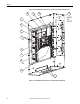
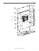
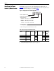
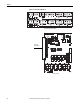
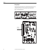
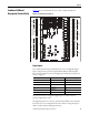
Table Of Contents
- Front Cover
- Important User Information
- Summary of Changes
- Table of Contents
- Introduction
- About the Drive
- Identifying the Drive by Cabinet Assembly ID Number
- LiquiFlo 2.0 Drive Component Locations
- Identifying the Power Module by Model Number
- AC Line I/O Board Description (Frame 3 Only)
- Standard I/O Board Description (Frame 3 Only)
- Combined I/O Board Description (Frame 4 Only)
- DPI Communication Ports
- Optional Equipment
- Planning the Installation
- Mounting The Power Module and Grounding the Drive
- Installing Input and Output Power Wiring
- Completing the Installation
- Using the Start-up Routines
- Programming Basics
- Parameter Descriptions
- Troubleshooting the Drive
- Verify that the DC Bus Capacitors are Discharged Before Servicing the Drive
- Determining Drive Status Using the Status LEDs
- About Alarms
- About Faults
- Diagnostic Parameters
- Common Symptoms and Corrective Actions
- Replacement Parts
- Board Replacement, Firmware Setup Procedures
- Troubleshooting the Drive Using the OIM
- Checking the Power Modules with Input Power Off
- Technical Specifications
- Using the OIM
- Installing and Removing the OIM
- Display Description
- OIM Menu Structure
- Powering Up and Adjusting the OIM
- Selecting a Device in the System
- Using the OIM to Program the Drive
- Monitoring the Drive Using the Process Display Screen on the OIM
- Displaying and Changing the OIM Reference
- Customizing the Process Display Screen
- Customizing the Function Keys
- Controlling the Drive From the OIM
- LiquiFlo 2.0 Drive Frame 3 Wiring Diagrams
- LiquiFlo 2.0 Drive Frame 4 Wiring Diagrams
- Index
- Back Cover

Rockwell Automation Publication D2-3518-3 - May 2013 25
Chapter 2
AC Line I/O Board Description
(Frame 3 Only)
The following signals are available at the AC Line I/O board terminal block. The
AC Line I/O board is labeled as item 21 in Figure 4
. See Figure 9 for terminal
identification.
Digital Inputs
The AC Line I/O board terminal block provides terminals for four digital inputs
(terminals 22...26). These digital inputs cannot be configured.
Digital Outputs
The AC Line I/O board terminal provides terminals for six digital outputs that
are non user-configurable terminals 5...16 and 27...32. The state of these six
outputs can be changed by writing to inverter parameter Appl Digital Out (30).
Digital output 1 is always connected to the shunt trip circuit; do not use digital
output 1 for anything else.
The digital output devices are form C relays capable of switching 250V AC at 8 A
or 30V DC at 8 A.
Analog Inputs
The AC Line I/O board contains no component hardware for user-configurable
analog inputs.
Analog Outputs
The AC Line I/O board terminal block provdes terminals for two special
purpose analog outputs, using terminals 1-2 and 17-18. These outputs are not
user-configurable.