
Owner's manual
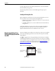
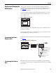
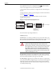
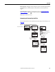
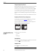

Table Of Contents
- Front Cover
- Important User Information
- Summary of Changes
- Table of Contents
- Introduction
- About the Drive
- Identifying the Drive by Cabinet Assembly ID Number
- LiquiFlo 2.0 Drive Component Locations
- Identifying the Power Module by Model Number
- AC Line I/O Board Description (Frame 3 Only)
- Standard I/O Board Description (Frame 3 Only)
- Combined I/O Board Description (Frame 4 Only)
- DPI Communication Ports
- Optional Equipment
- Planning the Installation
- Mounting The Power Module and Grounding the Drive
- Installing Input and Output Power Wiring
- Completing the Installation
- Using the Start-up Routines
- Programming Basics
- Parameter Descriptions
- Troubleshooting the Drive
- Verify that the DC Bus Capacitors are Discharged Before Servicing the Drive
- Determining Drive Status Using the Status LEDs
- About Alarms
- About Faults
- Diagnostic Parameters
- Common Symptoms and Corrective Actions
- Replacement Parts
- Board Replacement, Firmware Setup Procedures
- Troubleshooting the Drive Using the OIM
- Checking the Power Modules with Input Power Off
- Technical Specifications
- Using the OIM
- Installing and Removing the OIM
- Display Description
- OIM Menu Structure
- Powering Up and Adjusting the OIM
- Selecting a Device in the System
- Using the OIM to Program the Drive
- Monitoring the Drive Using the Process Display Screen on the OIM
- Displaying and Changing the OIM Reference
- Customizing the Process Display Screen
- Customizing the Function Keys
- Controlling the Drive From the OIM
- LiquiFlo 2.0 Drive Frame 3 Wiring Diagrams
- LiquiFlo 2.0 Drive Frame 4 Wiring Diagrams
- Index
- Back Cover
246 Rockwell Automation Publication D2-3518-3 - May 2013
Appendix B
Setting the Display Timeout Period
When the OIM is inactive (that is, no keys have been pressed) for a user-specified
period of time, the process display screen becomes active. To return to the
previously active screen, press any key. To return to the Main Menu, press .
To set the display timeout period, select Display Timeout from the Display
menu. The timeout period can range from 10...1200 seconds (20 minutes).
This feature can also be disabled by pressing the F1 key while in the display time
screen.
Note that each OIM connected to the drive can have a different timeout period.
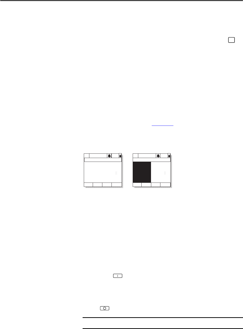
Using Reverse Video for the Process Display Screen
To select normal or reverse video for the process display screen, select Display
Video from the Display menu. See Figure 102
for sample screens.
Note that each OIM connected to the drive can have a different display mode.
Figure 102 - Selecting Reverse Video for the Process Display Screen
Controlling the Drive From
the OIM
The OIM can be used to control the drive:
• Start (Run)
• Stop
• Clear Faults
Starting the Drive
When start from the OIM is enabled using the Logic Mask (276) and Start Mask
(277), pressing issues a start command to the drive.
Stopping the Drive
Pressing issues a stop command to the drive.
ESC/
PROG
P0: LiquiFlo 2.0
Auto
Stopped
Fltq
0.00 Volts
Amps
Hz
0.00
0.00
Luse1
Normal Video
Reverse Video
P0: LiquiFlo 2.0
Auto
Stopped
Fltq
0.00 Volts
Amps
Hz
0.00
0.00
Luse1
IMPORTANT
Stop commands from any attached OIM are always enabled.