
Owner's manual
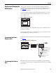
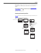


Table Of Contents
- Front Cover
- Important User Information
- Summary of Changes
- Table of Contents
- Introduction
- About the Drive
- Identifying the Drive by Cabinet Assembly ID Number
- LiquiFlo 2.0 Drive Component Locations
- Identifying the Power Module by Model Number
- AC Line I/O Board Description (Frame 3 Only)
- Standard I/O Board Description (Frame 3 Only)
- Combined I/O Board Description (Frame 4 Only)
- DPI Communication Ports
- Optional Equipment
- Planning the Installation
- Mounting The Power Module and Grounding the Drive
- Installing Input and Output Power Wiring
- Completing the Installation
- Using the Start-up Routines
- Programming Basics
- Parameter Descriptions
- Troubleshooting the Drive
- Verify that the DC Bus Capacitors are Discharged Before Servicing the Drive
- Determining Drive Status Using the Status LEDs
- About Alarms
- About Faults
- Diagnostic Parameters
- Common Symptoms and Corrective Actions
- Replacement Parts
- Board Replacement, Firmware Setup Procedures
- Troubleshooting the Drive Using the OIM
- Checking the Power Modules with Input Power Off
- Technical Specifications
- Using the OIM
- Installing and Removing the OIM
- Display Description
- OIM Menu Structure
- Powering Up and Adjusting the OIM
- Selecting a Device in the System
- Using the OIM to Program the Drive
- Monitoring the Drive Using the Process Display Screen on the OIM
- Displaying and Changing the OIM Reference
- Customizing the Process Display Screen
- Customizing the Function Keys
- Controlling the Drive From the OIM
- LiquiFlo 2.0 Drive Frame 3 Wiring Diagrams
- LiquiFlo 2.0 Drive Frame 4 Wiring Diagrams
- Index
- Back Cover
Rockwell Automation Publication D2-3518-3 - May 2013 245
Appendix B
Preset Speed 1...6: Toggles the selected preset speed on and off and grants Hand
(manual) reference control. Returns to Auto reference when the function is
toggled.
View Fault Queue: Displays the Fault Queue screen (see Accessing the Fault
Queue on page 226). Press to return to the process display screen.
Next: (Reserved for future use.)
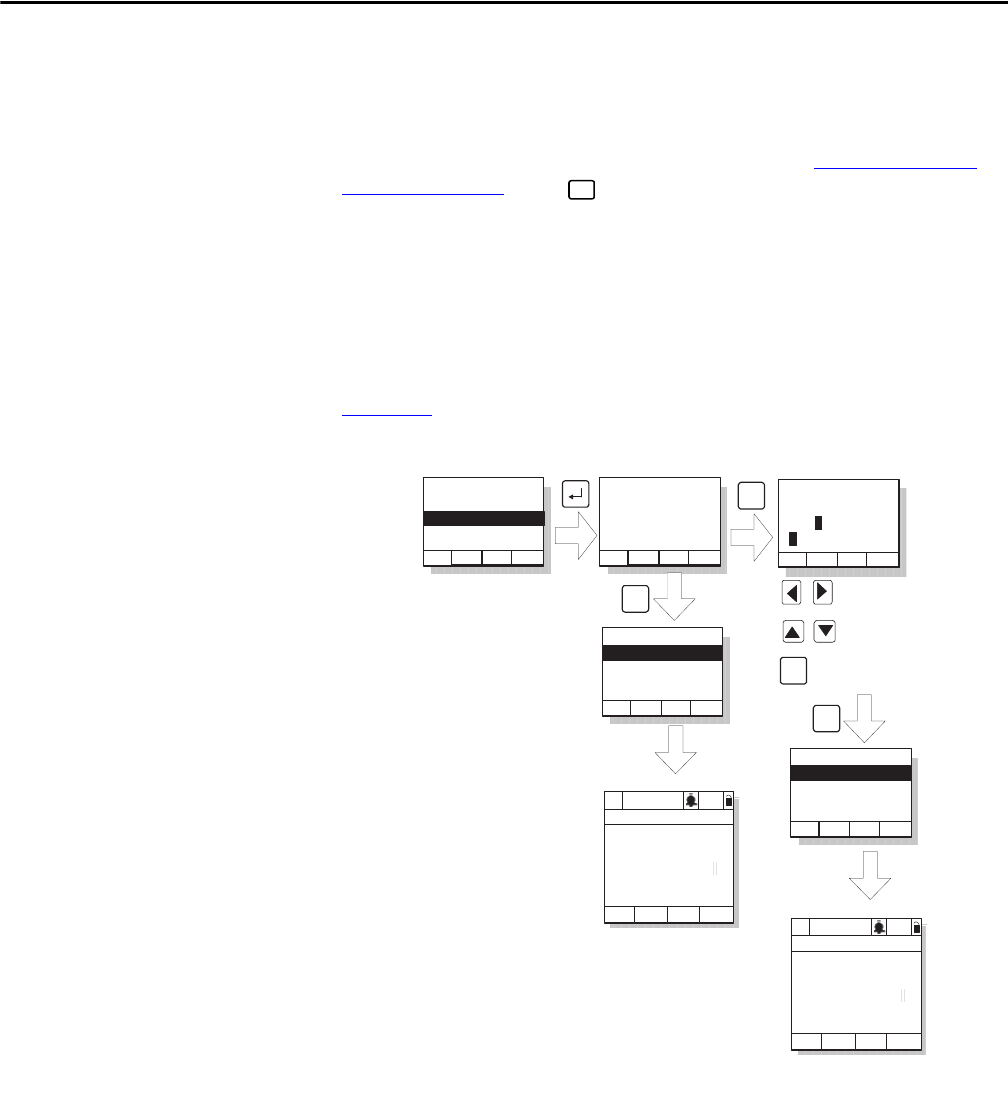
Customizing the Function Key Label Text
You can customize the text for each function key label (up to five characters). See
Figure 101
.
Figure 101 - Customizing the Function Key Label Text
ESC/
PROG
Function List:
Load User Set 1
Load User Set 2
Undefined
Do You Wish to
Rename Function
States Text For:
Load User Set 1
Yes No
Function List
F2: Undefined
F3: Undefined
F1: Load User Set 1
ClrFK
Name State Text:
FKey Text
LuseA
ABCDEFGHIJKLM
Next
F1
F2
OIM will use default
F-Key label Luse1
Function List
F2: Undefined
F3: Undefined
F1: Load User Set 1
ClrFK
F4
OIM will use custom
F-Key label LuseA
Move through label text
Move through letters and
symbols
P0: LiquiFlo 2.0
Auto
Stopped
Fltq
0.00 Volts
Amps
Hz
0.00
0.00
Luse1
P0: LiquiFlo 2.0
Auto
Stopped
Fltq
0.00 Volts
Amps
Hz
0.00
0.00
LuseA
A->a
Save
F3
Esc or timeout to
Process Display
screen
Esc or timeout to
Process Display
screen
From previous figure
Toggle between upper
and lower case