
Owner's manual
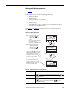
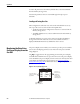
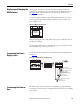
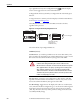
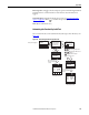
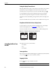

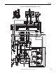

Table Of Contents
- Front Cover
- Important User Information
- Summary of Changes
- Table of Contents
- Introduction
- About the Drive
- Identifying the Drive by Cabinet Assembly ID Number
- LiquiFlo 2.0 Drive Component Locations
- Identifying the Power Module by Model Number
- AC Line I/O Board Description (Frame 3 Only)
- Standard I/O Board Description (Frame 3 Only)
- Combined I/O Board Description (Frame 4 Only)
- DPI Communication Ports
- Optional Equipment
- Planning the Installation
- Mounting The Power Module and Grounding the Drive
- Installing Input and Output Power Wiring
- Completing the Installation
- Using the Start-up Routines
- Programming Basics
- Parameter Descriptions
- Troubleshooting the Drive
- Verify that the DC Bus Capacitors are Discharged Before Servicing the Drive
- Determining Drive Status Using the Status LEDs
- About Alarms
- About Faults
- Diagnostic Parameters
- Common Symptoms and Corrective Actions
- Replacement Parts
- Board Replacement, Firmware Setup Procedures
- Troubleshooting the Drive Using the OIM
- Checking the Power Modules with Input Power Off
- Technical Specifications
- Using the OIM
- Installing and Removing the OIM
- Display Description
- OIM Menu Structure
- Powering Up and Adjusting the OIM
- Selecting a Device in the System
- Using the OIM to Program the Drive
- Monitoring the Drive Using the Process Display Screen on the OIM
- Displaying and Changing the OIM Reference
- Customizing the Process Display Screen
- Customizing the Function Keys
- Controlling the Drive From the OIM
- LiquiFlo 2.0 Drive Frame 3 Wiring Diagrams
- LiquiFlo 2.0 Drive Frame 4 Wiring Diagrams
- Index
- Back Cover
Rockwell Automation Publication D2-3518-3 - May 2013 243
Appendix B
Displaying and Changing the
OIM Reference
You can display the reference value that the OIM is sending to the drive by
pressing the up or down arrow key once when the process display screen is active.
See Figure 98
. The OIM reference can be used for the speed reference, PI
reference, or trim reference.
To change the displayed reference, press and hold down either the up or down
arrow key until the desired value is displayed. Release the key to return to the
process display screen.
Figure 98 - OIM Reference Displayed
Note that changing the value of the OIM reference does not affect the value of
any other port reference.
The value of the OIM reference is saved through a power cycle if parameter 192
(Save OIM Ref ) is set to save at power down.
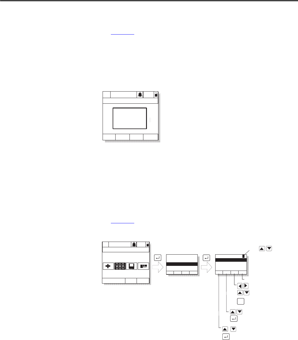
Customizing the Process
Display Screen
To customize the process display screen, select Monitor from the Display menu.
See Figure 99
.
Figure 99 - Customizing the Process Display Screen
Customizing the Function
Keys
The function keys (F1, F2, F3, and F4, also called F-Keys) on the OIM can be
customized to perform several pre-configured functions when the process display
screen is active.
P0: LiquiFlo 2.0
Auto
Stopped
Fltq
0.00 Volts
Amps
Hz
0.00
0.00
OIM Ref
0.00 Hz
Monitor Lang
P0: LiquiFlo 2.0
Auto
Stopped
Main Menu
Display
Display:
Language
Function Keys
Monitor
Dispy: Dspy Ln#
Scale:
Text:
Par: #
Param Scale
Text Save
Use
to select display
line 1, 2, or 3
Press F4 to save
Adjust scale
Accept scaling value
Scroll through parameter
numbers
Select parameter
Move through label text
Move through letters
and symbols
F3
Toggle between upper
and lower case