
Owner's manual
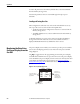
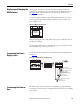
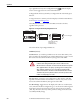
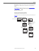

Table Of Contents
- Front Cover
- Important User Information
- Summary of Changes
- Table of Contents
- Introduction
- About the Drive
- Identifying the Drive by Cabinet Assembly ID Number
- LiquiFlo 2.0 Drive Component Locations
- Identifying the Power Module by Model Number
- AC Line I/O Board Description (Frame 3 Only)
- Standard I/O Board Description (Frame 3 Only)
- Combined I/O Board Description (Frame 4 Only)
- DPI Communication Ports
- Optional Equipment
- Planning the Installation
- Mounting The Power Module and Grounding the Drive
- Installing Input and Output Power Wiring
- Completing the Installation
- Using the Start-up Routines
- Programming Basics
- Parameter Descriptions
- Troubleshooting the Drive
- Verify that the DC Bus Capacitors are Discharged Before Servicing the Drive
- Determining Drive Status Using the Status LEDs
- About Alarms
- About Faults
- Diagnostic Parameters
- Common Symptoms and Corrective Actions
- Replacement Parts
- Board Replacement, Firmware Setup Procedures
- Troubleshooting the Drive Using the OIM
- Checking the Power Modules with Input Power Off
- Technical Specifications
- Using the OIM
- Installing and Removing the OIM
- Display Description
- OIM Menu Structure
- Powering Up and Adjusting the OIM
- Selecting a Device in the System
- Using the OIM to Program the Drive
- Monitoring the Drive Using the Process Display Screen on the OIM
- Displaying and Changing the OIM Reference
- Customizing the Process Display Screen
- Customizing the Function Keys
- Controlling the Drive From the OIM
- LiquiFlo 2.0 Drive Frame 3 Wiring Diagrams
- LiquiFlo 2.0 Drive Frame 4 Wiring Diagrams
- Index
- Back Cover
Rockwell Automation Publication D2-3518-3 - May 2013 241
Appendix B
Viewing and Adjusting Parameters
See Chapter 8 for information on how to access the parameters in the drive.
Each parameter screen contains the following information:
• Parameter number
• Parameter name
• Current parameter value and units
• Parameter range
• F1 key defined as a toggle to enable you to view the parameter’s current
value and the factory-default value
See Figure 96
and Tabl e 37 for instructions on how to adjust the parameter
values.
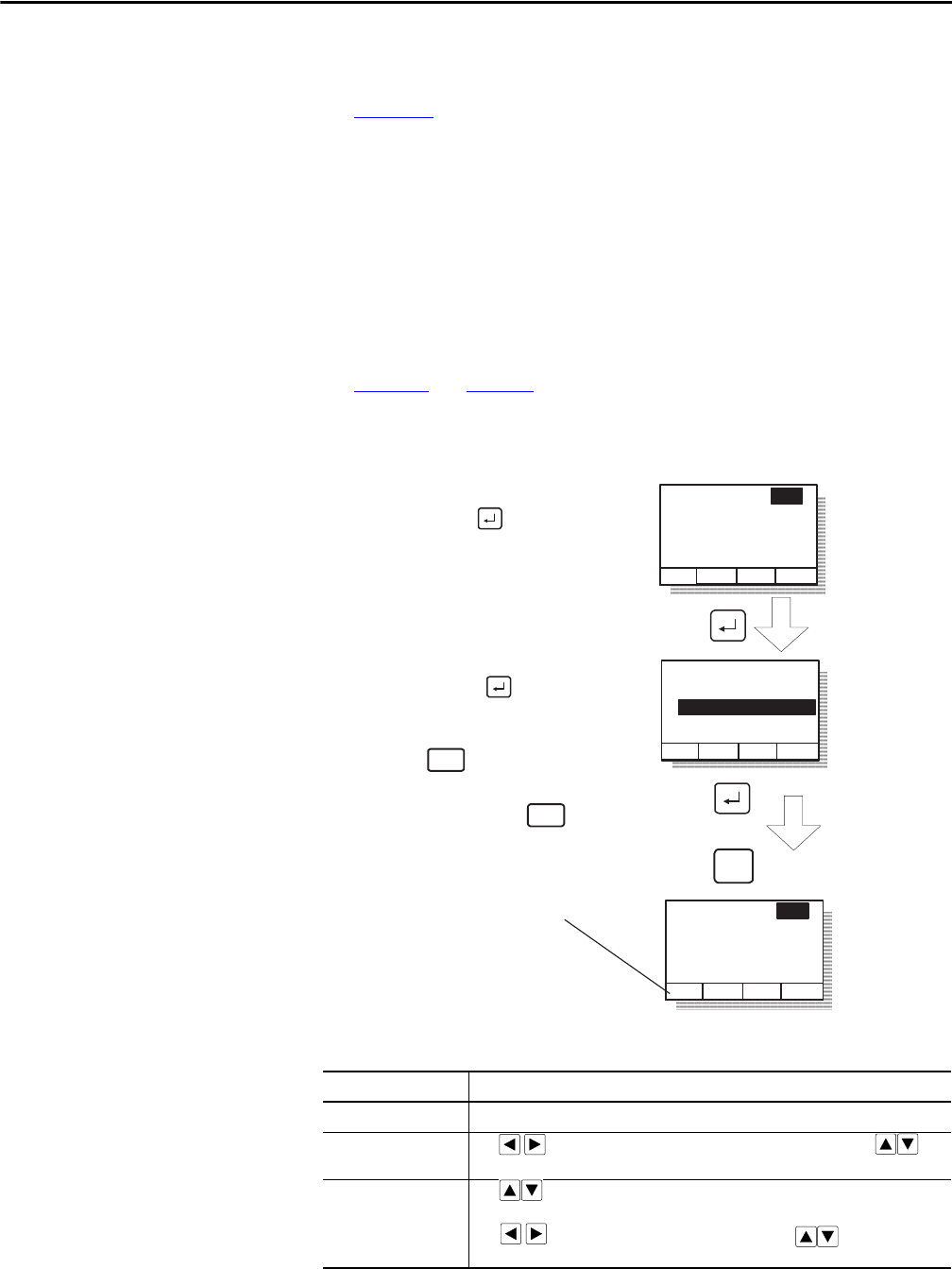
Figure 96 - Adjusting Parameters
Table 37 - Adjusting Parameters, Arrow Key Functions
Parameter Type How to Adjust
Numbered List Use up/down arrow keys to advance through the list of options.
Bit Use to move the cursor to the bit location you want to change. Use to
change the value of the bit.
Numeric Use to increase or decrease the value.
- Or -
Use to move the cursor from digit to digit, and use to increase or
decrease the value of the digit.
Parameter: #
Parameter Name
Lower limit< >Upper limit
Value Units
Dflt
nnn
Parameter: #
Parameter Name
Lower limit< >Upper limit
Value Units
Dflt
nnn
Save change
Don't save
change
ESC/
PROG
Step 1. At the parameter entry
screen, press to
highlight the parameter
value.
- OR -
Parameter: #
Parameter Name
Lower limit< >Upper limit
Value Units
Dflt
nnn
Step 2. Adjust the parameter
value (see table B.2),
and then press
to save the value.
ESC/
PROG
If you do not want to save the
value, press to return to the
initial parameter screen. You can
then repeat steps 1 and 2 to
change the value, or press
to back out of this menu.
ESC/
PROG
(The screen shown here was
accessed using the
Parameters>P Numbers path)
The F1 key is defined as a
toggle to enable you to view the
parameter's current value and
the factory-default value.