
Owner's manual
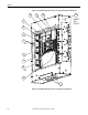
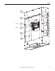
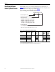
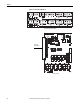
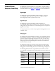
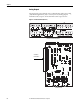
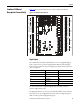
Table Of Contents
- Front Cover
- Important User Information
- Summary of Changes
- Table of Contents
- Introduction
- About the Drive
- Identifying the Drive by Cabinet Assembly ID Number
- LiquiFlo 2.0 Drive Component Locations
- Identifying the Power Module by Model Number
- AC Line I/O Board Description (Frame 3 Only)
- Standard I/O Board Description (Frame 3 Only)
- Combined I/O Board Description (Frame 4 Only)
- DPI Communication Ports
- Optional Equipment
- Planning the Installation
- Mounting The Power Module and Grounding the Drive
- Installing Input and Output Power Wiring
- Completing the Installation
- Using the Start-up Routines
- Programming Basics
- Parameter Descriptions
- Troubleshooting the Drive
- Verify that the DC Bus Capacitors are Discharged Before Servicing the Drive
- Determining Drive Status Using the Status LEDs
- About Alarms
- About Faults
- Diagnostic Parameters
- Common Symptoms and Corrective Actions
- Replacement Parts
- Board Replacement, Firmware Setup Procedures
- Troubleshooting the Drive Using the OIM
- Checking the Power Modules with Input Power Off
- Technical Specifications
- Using the OIM
- Installing and Removing the OIM
- Display Description
- OIM Menu Structure
- Powering Up and Adjusting the OIM
- Selecting a Device in the System
- Using the OIM to Program the Drive
- Monitoring the Drive Using the Process Display Screen on the OIM
- Displaying and Changing the OIM Reference
- Customizing the Process Display Screen
- Customizing the Function Keys
- Controlling the Drive From the OIM
- LiquiFlo 2.0 Drive Frame 3 Wiring Diagrams
- LiquiFlo 2.0 Drive Frame 4 Wiring Diagrams
- Index
- Back Cover
24 Rockwell Automation Publication D2-3518-3 - May 2013
Chapter 2
Identifying the Power
Module by Model Number
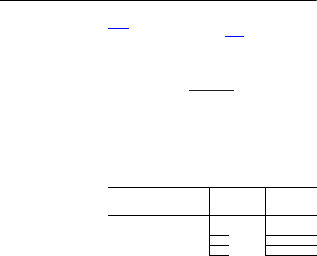
Each LiquiFlo 2.0 AC power module is identified by its model number. See
Figure 8
. This number appears on the shipping label and on the nameplate of the
power module. Power ratings are provided in Ta bl e 2
.
Figure 8 - Identifying the Power Module Model Number
Table 2 - Drive Assembly and Power Module Ratings
Drive Assembly ID
Number
Power Module
Model Number
Enclosure
Rating
Input
Power
(KVA)
Input Voltage
(V)
Input
Current
(2)
(Amps)
(2) 460 A with refrigerant, 405 A with water as coolant.
Output
Current
at 2 kHz
(3)
(Amps)
(3) 110% output current capability for one minute, 150% output current capability for 5 sec.
180264-A03 LF200460AAR NEMA 1 337 480 ±10% 405 405
180264-A06 LF200608CCR 505 608 608
180580-A07 LF200900CCR 673 900 900
180580-A09
(1)
(1) No overload rating for 180580-A09. 100% output current capability.
LF201215CCR 1010 1215 1215
LF20 0608CC R
LF20 = LiquiFlo 2.0
Continuous Ampere Rating
and Frame Size
0460AA = 405 amps*, frame 2AA
0608CC = 608 amps, frame 2CC
0900CC = 900 amps, frame 4AA
1215CC = 1215 amps, frame 4CC
Cooling Method
R = refrigerant/water
* 460 A with refrigerant, 405 A with water as coolant