
Owner's manual


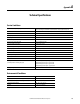
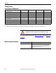
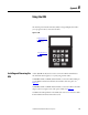
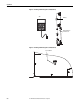
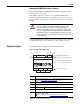
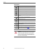
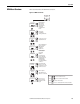
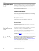
Table Of Contents
- Front Cover
- Important User Information
- Summary of Changes
- Table of Contents
- Introduction
- About the Drive
- Identifying the Drive by Cabinet Assembly ID Number
- LiquiFlo 2.0 Drive Component Locations
- Identifying the Power Module by Model Number
- AC Line I/O Board Description (Frame 3 Only)
- Standard I/O Board Description (Frame 3 Only)
- Combined I/O Board Description (Frame 4 Only)
- DPI Communication Ports
- Optional Equipment
- Planning the Installation
- Mounting The Power Module and Grounding the Drive
- Installing Input and Output Power Wiring
- Completing the Installation
- Using the Start-up Routines
- Programming Basics
- Parameter Descriptions
- Troubleshooting the Drive
- Verify that the DC Bus Capacitors are Discharged Before Servicing the Drive
- Determining Drive Status Using the Status LEDs
- About Alarms
- About Faults
- Diagnostic Parameters
- Common Symptoms and Corrective Actions
- Replacement Parts
- Board Replacement, Firmware Setup Procedures
- Troubleshooting the Drive Using the OIM
- Checking the Power Modules with Input Power Off
- Technical Specifications
- Using the OIM
- Installing and Removing the OIM
- Display Description
- OIM Menu Structure
- Powering Up and Adjusting the OIM
- Selecting a Device in the System
- Using the OIM to Program the Drive
- Monitoring the Drive Using the Process Display Screen on the OIM
- Displaying and Changing the OIM Reference
- Customizing the Process Display Screen
- Customizing the Function Keys
- Controlling the Drive From the OIM
- LiquiFlo 2.0 Drive Frame 3 Wiring Diagrams
- LiquiFlo 2.0 Drive Frame 4 Wiring Diagrams
- Index
- Back Cover
Rockwell Automation Publication D2-3518-3 - May 2013 239
Appendix B
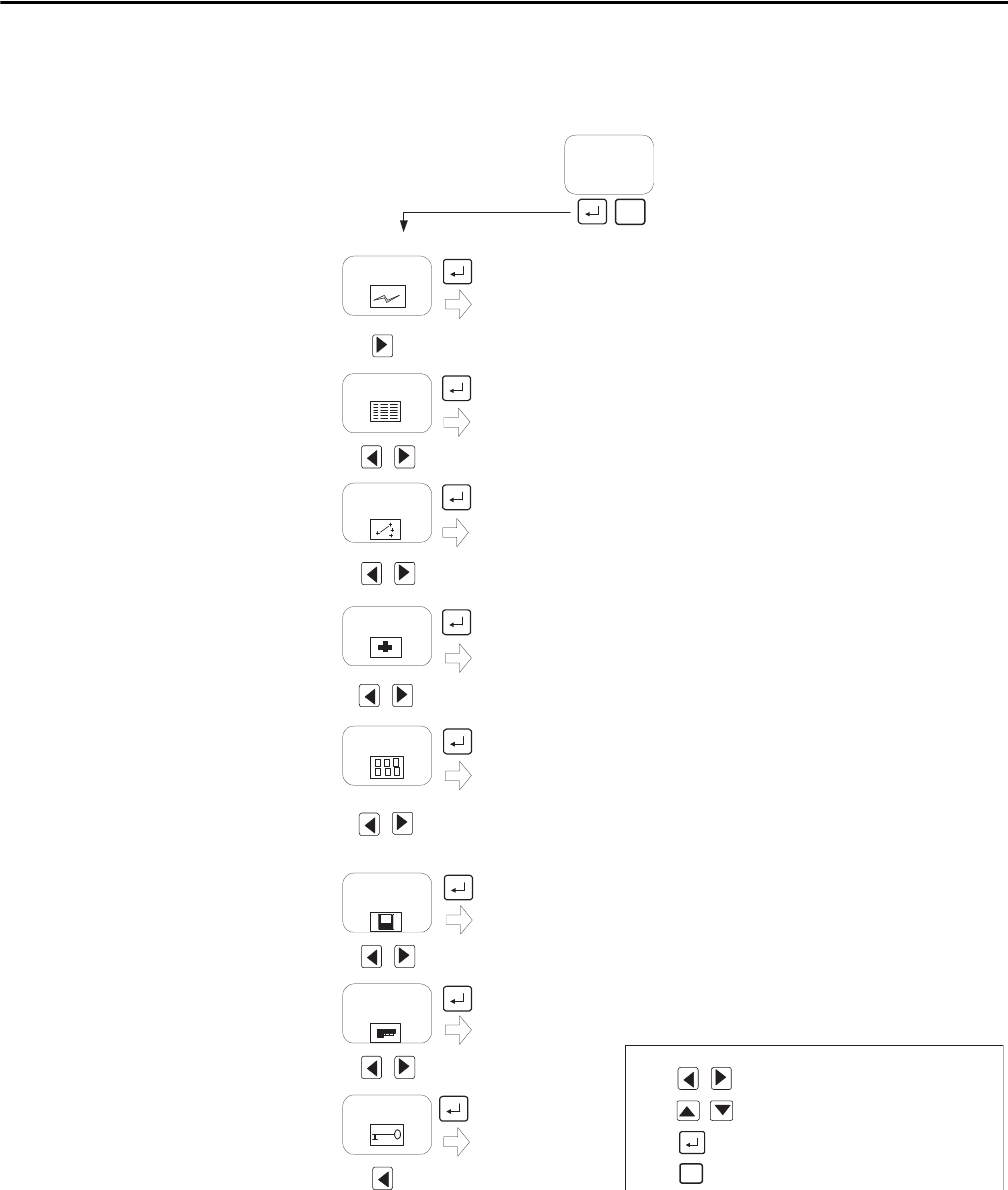
OIM Menu Structure
This section describes the OIM menu structure.
Figure 95 - OIM Menu Structure
Start-Up
Parameters
Control Src
Sel
Diagnostics
Display
Memory
Storage
Device
Select
User
Display
By Groups
Changed Params
P Numbers
Speed Ref A Sel
Logic Source Sel
Password
Load Frm Usr Set
Save to User Set
Reset Defaults
Active User Set
Language
Function Keys
Reset Display
Display Video
Display Timeout
Monitor
Device Identity
Fast PwrUp Mode
Contrast
Set Wrt Prot PW
Set Acc Lvl PW
Set Access Lvl
QuickStart
Motor Data
Configure I/O
Ref Setup
Speed Limits
Input Voltage
Motor Tests
Done
ESC/
PROG
Press
Press
Press
to move between menu items
to select a menu item
to move 1 level back in the menu structure
ESC/
PROG
Logout
Menu options
dependent upon
devices connected.
Press to move between icons
OIM Version
Device Version
View Fault Queue
Device Items
Status Info
Fault Info
Tech Support