
Owner's manual


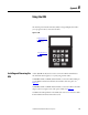
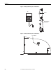
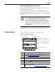
Table Of Contents
- Front Cover
- Important User Information
- Summary of Changes
- Table of Contents
- Introduction
- About the Drive
- Identifying the Drive by Cabinet Assembly ID Number
- LiquiFlo 2.0 Drive Component Locations
- Identifying the Power Module by Model Number
- AC Line I/O Board Description (Frame 3 Only)
- Standard I/O Board Description (Frame 3 Only)
- Combined I/O Board Description (Frame 4 Only)
- DPI Communication Ports
- Optional Equipment
- Planning the Installation
- Mounting The Power Module and Grounding the Drive
- Installing Input and Output Power Wiring
- Completing the Installation
- Using the Start-up Routines
- Programming Basics
- Parameter Descriptions
- Troubleshooting the Drive
- Verify that the DC Bus Capacitors are Discharged Before Servicing the Drive
- Determining Drive Status Using the Status LEDs
- About Alarms
- About Faults
- Diagnostic Parameters
- Common Symptoms and Corrective Actions
- Replacement Parts
- Board Replacement, Firmware Setup Procedures
- Troubleshooting the Drive Using the OIM
- Checking the Power Modules with Input Power Off
- Technical Specifications
- Using the OIM
- Installing and Removing the OIM
- Display Description
- OIM Menu Structure
- Powering Up and Adjusting the OIM
- Selecting a Device in the System
- Using the OIM to Program the Drive
- Monitoring the Drive Using the Process Display Screen on the OIM
- Displaying and Changing the OIM Reference
- Customizing the Process Display Screen
- Customizing the Function Keys
- Controlling the Drive From the OIM
- LiquiFlo 2.0 Drive Frame 3 Wiring Diagrams
- LiquiFlo 2.0 Drive Frame 4 Wiring Diagrams
- Index
- Back Cover
Rockwell Automation Publication D2-3518-3 - May 2013 237
Appendix B
Removing the OIM While the Drive is Powered
If the OIM is the selected control source, removing the OIM while the drive is
powered will cause a drive fault.
If the OIM is not the selected control source, but is the reference source,
removing the OIM while the drive is powered will result in a zero reference value.
When the OIM is replaced, the drive will ramp to the reference level supplied by
the OIM.
If the LCD OIM is not the selected control source or reference source, removing
the OIM while the drive is powered will have no effect on drive operation.
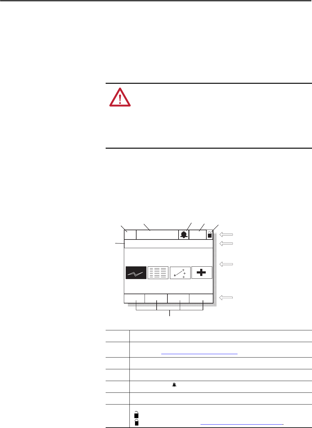
Display Description
This section describes the display features and the key functions.
Figure 94 - The Display (Main Menu Shown)
ATTENTION: Removing and replacing the LCD OIM while the drive is running
may cause an abrupt speed change if the LCD OIM is the selected reference
source, but is not the selected control source. The drive will ramp to the
reference level provided by the OIM at the rate specified in Accel Time 1 (140),
Accel Time 2 (141), Decel Time 1 (142) and Decel Time 2 (143). Be aware that an
abrupt speed change may occur depending upon the new reference level and
the rate specified in these parameters. Failure to observe this precaution could
result in bodily injury.
①
Function Key (F1, F2, F3, F4) definitions
✍
Port/peripheral identification. Identifies port or peripheral on DPI about which the OIM is displaying
information. See Selecting a Device in the System
on page 240.
③
PI loop status: PI = PI control is active.
④
Operating status (for example, Running, Stopped, etc.)
⑤
Alarm annunciation. = Alarm has occurred.
⑥
Auto/Hand mode status.
⑦
Write-protect password status:
(unlocked) = password disabled;
(locked) = password enabled. See Selecting the Parameter Access Level
on page 63.
P0: LiquiFlo 2.0
PI
Auto
Stopped
Main Menu
Start-Up
➀
➁
➂
➃
➄
➅
Operational Status Line
Menu, Programming Screen,
or Process (User) Display
Device Selected/Error Text
Function Key LineLang
➆