
Owner's manual


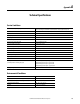
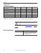
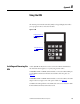
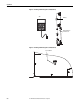
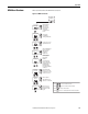
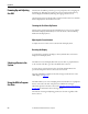
Table Of Contents
- Front Cover
- Important User Information
- Summary of Changes
- Table of Contents
- Introduction
- About the Drive
- Identifying the Drive by Cabinet Assembly ID Number
- LiquiFlo 2.0 Drive Component Locations
- Identifying the Power Module by Model Number
- AC Line I/O Board Description (Frame 3 Only)
- Standard I/O Board Description (Frame 3 Only)
- Combined I/O Board Description (Frame 4 Only)
- DPI Communication Ports
- Optional Equipment
- Planning the Installation
- Mounting The Power Module and Grounding the Drive
- Installing Input and Output Power Wiring
- Completing the Installation
- Using the Start-up Routines
- Programming Basics
- Parameter Descriptions
- Troubleshooting the Drive
- Verify that the DC Bus Capacitors are Discharged Before Servicing the Drive
- Determining Drive Status Using the Status LEDs
- About Alarms
- About Faults
- Diagnostic Parameters
- Common Symptoms and Corrective Actions
- Replacement Parts
- Board Replacement, Firmware Setup Procedures
- Troubleshooting the Drive Using the OIM
- Checking the Power Modules with Input Power Off
- Technical Specifications
- Using the OIM
- Installing and Removing the OIM
- Display Description
- OIM Menu Structure
- Powering Up and Adjusting the OIM
- Selecting a Device in the System
- Using the OIM to Program the Drive
- Monitoring the Drive Using the Process Display Screen on the OIM
- Displaying and Changing the OIM Reference
- Customizing the Process Display Screen
- Customizing the Function Keys
- Controlling the Drive From the OIM
- LiquiFlo 2.0 Drive Frame 3 Wiring Diagrams
- LiquiFlo 2.0 Drive Frame 4 Wiring Diagrams
- Index
- Back Cover

Rockwell Automation Publication D2-3518-3 - May 2013 235
Appendix B
Using the OIM
The LCD Operator Interface Module (OIM) is a keypad/display that enables
you to program, monitor, and control the drive.
Figure 91 - OIM
Installing and Removing the
OIM
A cable (RECBL-LCD) must be used to convert the OIM for hand-held use.
The maximum cable length is 9.7 m (32 ft) using extender cables.
To install the OIM on a Frame 3 Power Module, connect the OIM to DPI port
3 on the DPI Communication Interface board until it clicks into place. See
Figure 92
.
To install the OIM on a Frame 4 Power Module, connect the OIM to the OIM
adapter on the lower right corner of the power module. See Figure 93
.
To remove the OIM, pull back on the OIM cable connector to release the OIM
from the DPI Communication Interface board.
tex
t
F1
ESC/
PROG
HAND AUTO
F2 F3 F4
o
I
See Display Description on
page 237 for information
abut the display.
See Key Descriptions on
page 238 for information
abut the keys.