
Owner's manual


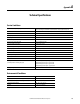
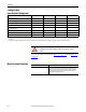
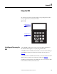
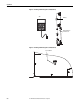
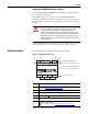
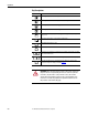
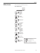
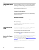
Table Of Contents
- Front Cover
- Important User Information
- Summary of Changes
- Table of Contents
- Introduction
- About the Drive
- Identifying the Drive by Cabinet Assembly ID Number
- LiquiFlo 2.0 Drive Component Locations
- Identifying the Power Module by Model Number
- AC Line I/O Board Description (Frame 3 Only)
- Standard I/O Board Description (Frame 3 Only)
- Combined I/O Board Description (Frame 4 Only)
- DPI Communication Ports
- Optional Equipment
- Planning the Installation
- Mounting The Power Module and Grounding the Drive
- Installing Input and Output Power Wiring
- Completing the Installation
- Using the Start-up Routines
- Programming Basics
- Parameter Descriptions
- Troubleshooting the Drive
- Verify that the DC Bus Capacitors are Discharged Before Servicing the Drive
- Determining Drive Status Using the Status LEDs
- About Alarms
- About Faults
- Diagnostic Parameters
- Common Symptoms and Corrective Actions
- Replacement Parts
- Board Replacement, Firmware Setup Procedures
- Troubleshooting the Drive Using the OIM
- Checking the Power Modules with Input Power Off
- Technical Specifications
- Using the OIM
- Installing and Removing the OIM
- Display Description
- OIM Menu Structure
- Powering Up and Adjusting the OIM
- Selecting a Device in the System
- Using the OIM to Program the Drive
- Monitoring the Drive Using the Process Display Screen on the OIM
- Displaying and Changing the OIM Reference
- Customizing the Process Display Screen
- Customizing the Function Keys
- Controlling the Drive From the OIM
- LiquiFlo 2.0 Drive Frame 3 Wiring Diagrams
- LiquiFlo 2.0 Drive Frame 4 Wiring Diagrams
- Index
- Back Cover
234 Rockwell Automation Publication D2-3518-3 - May 2013
Appendix A
Cooling System
Specifications (Refrigerant)
For coolant hardware connections, see Figure 14 on page 37 through Figure 17
on page 40.
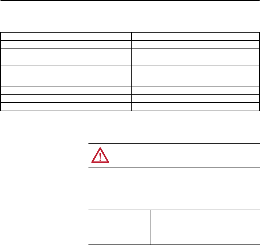
Motor Overload Protection
LF200460AAR LF200608CCR LF200900CCR LF201215CCR
Max. Input Current (Amps) 405 608 900 1215
Max. Output Current (Amps) 405 608 900 1215
Coolant Temp Range
(1)
5...40 °C (41...104 °F) 5...40 °C (41...104 °F) 5...40 °C (41...104 °F) 5...40 °C (41...104 °F)
Minimum Coolant Flow Rate (GPM) 7 7 15 15
Pressure Drop (psig) from Power Module Inlet to Outlet @
Min. Coolant Flow Rate
10 10 10 10
Coolant WEG25
(2)
WEG25
(2)
WEG25
(2)
WEG25
(2)
Max. Inlet Pressure (PSI) 180 180 180 180
Max. Heat Load 6000 Watts 9000 Watts 12,000 Watts 18,000 Watts
(1) Coolant temperature must be above the dew point to prevent condensation. If the water temperature is below the dew point, the appropriate water flow rate control is needed. Consult Rockwell
Automation.
(2) WEG25 = good quality or distilled water/ethylene glycol 25% by volume. An approved inhibited, silicate-free ethylene glycol is Ucartherm, a product of Dow Chemical Company.
ATTENTION: Ethylene glycol solutions must be inhibited and silicate-free. Use
of uninhibited and silicate-containing solutions can damage the cooling
system.
Condition Specification
Electronic Motor Overload Protection: Provides class 10 motor overload protection according to NEC article 430.
Does not provide speed sensitive overload protection, thermal memory
retention and motor over-temperature sensing according to NEC article
430.126 (A) (2). If such protection is needed in the end-use product, it
must be provided by additional means.