
Owner's manual


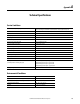
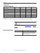
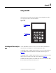
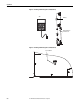
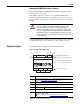
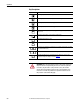
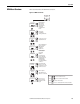
Table Of Contents
- Front Cover
- Important User Information
- Summary of Changes
- Table of Contents
- Introduction
- About the Drive
- Identifying the Drive by Cabinet Assembly ID Number
- LiquiFlo 2.0 Drive Component Locations
- Identifying the Power Module by Model Number
- AC Line I/O Board Description (Frame 3 Only)
- Standard I/O Board Description (Frame 3 Only)
- Combined I/O Board Description (Frame 4 Only)
- DPI Communication Ports
- Optional Equipment
- Planning the Installation
- Mounting The Power Module and Grounding the Drive
- Installing Input and Output Power Wiring
- Completing the Installation
- Using the Start-up Routines
- Programming Basics
- Parameter Descriptions
- Troubleshooting the Drive
- Verify that the DC Bus Capacitors are Discharged Before Servicing the Drive
- Determining Drive Status Using the Status LEDs
- About Alarms
- About Faults
- Diagnostic Parameters
- Common Symptoms and Corrective Actions
- Replacement Parts
- Board Replacement, Firmware Setup Procedures
- Troubleshooting the Drive Using the OIM
- Checking the Power Modules with Input Power Off
- Technical Specifications
- Using the OIM
- Installing and Removing the OIM
- Display Description
- OIM Menu Structure
- Powering Up and Adjusting the OIM
- Selecting a Device in the System
- Using the OIM to Program the Drive
- Monitoring the Drive Using the Process Display Screen on the OIM
- Displaying and Changing the OIM Reference
- Customizing the Process Display Screen
- Customizing the Function Keys
- Controlling the Drive From the OIM
- LiquiFlo 2.0 Drive Frame 3 Wiring Diagrams
- LiquiFlo 2.0 Drive Frame 4 Wiring Diagrams
- Index
- Back Cover

Rockwell Automation Publication D2-3518-3 - May 2013 233
Appendix A
Technical Specifications
Service Conditions
Environmental Conditions
AC Line Distribution System Capacity (maximum) for 480V AC Units Symmetrical fault current capacity: 85,000 A
Short circuit rating if a circuit breaker is used instead of fuses: 65,000 A (optional 100,000 A)
Control Method Sinusoidal pulse-width-modulated (PWM)
Displacement Power Factor
≥0.99
Line Frequency 50/60 Hz (
±2 Hz)
Line Voltage Variation -10...10%
Motor Lead Lengths 76 m (250 ft) total
Remote Operator Control Wire Length Up to 1 m (3 ft) from the drive
Analog Speed Reference Resolution 1/4096 (12 bits) 0.025%
Acceleration Adjustment Range 0.1...100.0 seconds (within the ability of current)
Carrier Frequency 2 kHz, 3 kHz, or 4 kHz (software-selectable)
Current Limit Adjustment 25...150% of drive rated amps
Service Factor 1.0
Speed Adjustable Range From 0 Hz to maximum speed
Speed Regulation Motor slip dependent
Speed Reference Resolution 0.01 with OIM,
±32767 counts with a network reference
Assembly Max Air Heat Load
(Heat Dissipated Into Surrounding Air, approx)
LF2 480V AC Input, 405 A output = approx 1800 W
LF2 480V AC Input, 608 A output = approx 2700 W
LF2 480V AC Input, 900 A output = approx 4000 W
LF2 480V AC Input, 1215 A output = approx 5300 W
Max Input Voltage Imbalance Service factor = 1.0
Condition Specification
Operating Temperature (inside NEMA/UL Type 1 enclosure) 0...+55 °C (32...131 °F)
Operating Temperature (outside NEMA/UL Type 1 enclosure) 0...40 °C (32...104 °F)
Storage Temperature (ambient) −40...65 °C (−40...149 °F)
Humidity 5...95% (non-condensing)